Electromagnetic shielding cabinet with shockproof function

An electromagnetic shielding and cabinet technology, which is applied in the directions of magnetic field/electric field shielding, casing/cabinet/drawer components, electrical equipment casing/cabinet/drawer, etc., can solve the problem of simple heat dissipation structure, damage to the internal circuit structure of the cabinet and computer The main body, reducing the heat dissipation efficiency of the cabinet, etc.

Inactive Publication Date: 2021-09-10
东台市苏宝电磁屏蔽设备有限公司
View PDF0 Cites 0 Cited by
  • Summary
  • Abstract
  • Description
  • Claims
  • Application Information

AI Technical Summary

Problems solved by technology

[0004] The object of the present invention is to provide an electromagnetic shielding cabinet with anti-shock function to solve the problem that the electromagnetic shielding cabinet proposed in the above background technology will generate a lot of heat when it is in use. Use will cause blockage, reduce the heat dissipation efficiency of the cabinet, and in the long run will damage the circuit structure inside the cabinet and the main body of the computer, and the adjustment of the placement plate inside the traditional electromagnetic shielding cabinet is more troublesome, resulting in damage to the electrical components inside the electromagnetic shielding cabinet Maintenance and replacement will waste a lot of time. At the same time, when moving the electromagnetic shielding cabinet, it is easy to cause bumps, causing the equipment inside the cabinet to shake.

Method used


Image

  • Electromagnetic shielding cabinet with shockproof function
  • Electromagnetic shielding cabinet with shockproof function
  • Electromagnetic shielding cabinet with shockproof function

Examples


Embodiment Construction

[0030] The following will clearly and completely describe the technical solutions in the embodiments of the present invention with reference to the accompanying drawings in the embodiments of the present invention. Obviously, the described embodiments are only some, not all, embodiments of the present invention. Based on the embodiments of the present invention, all other embodiments obtained by persons of ordinary skill in the art without making creative efforts belong to the protection scope of the present invention.

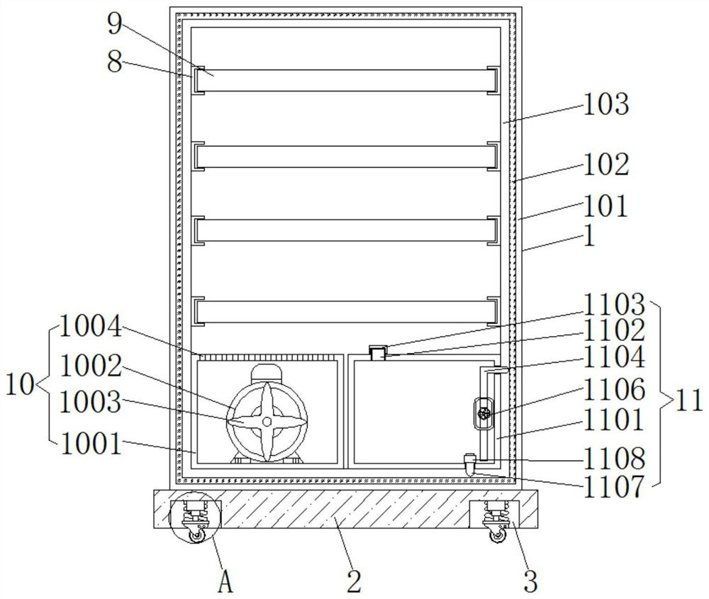
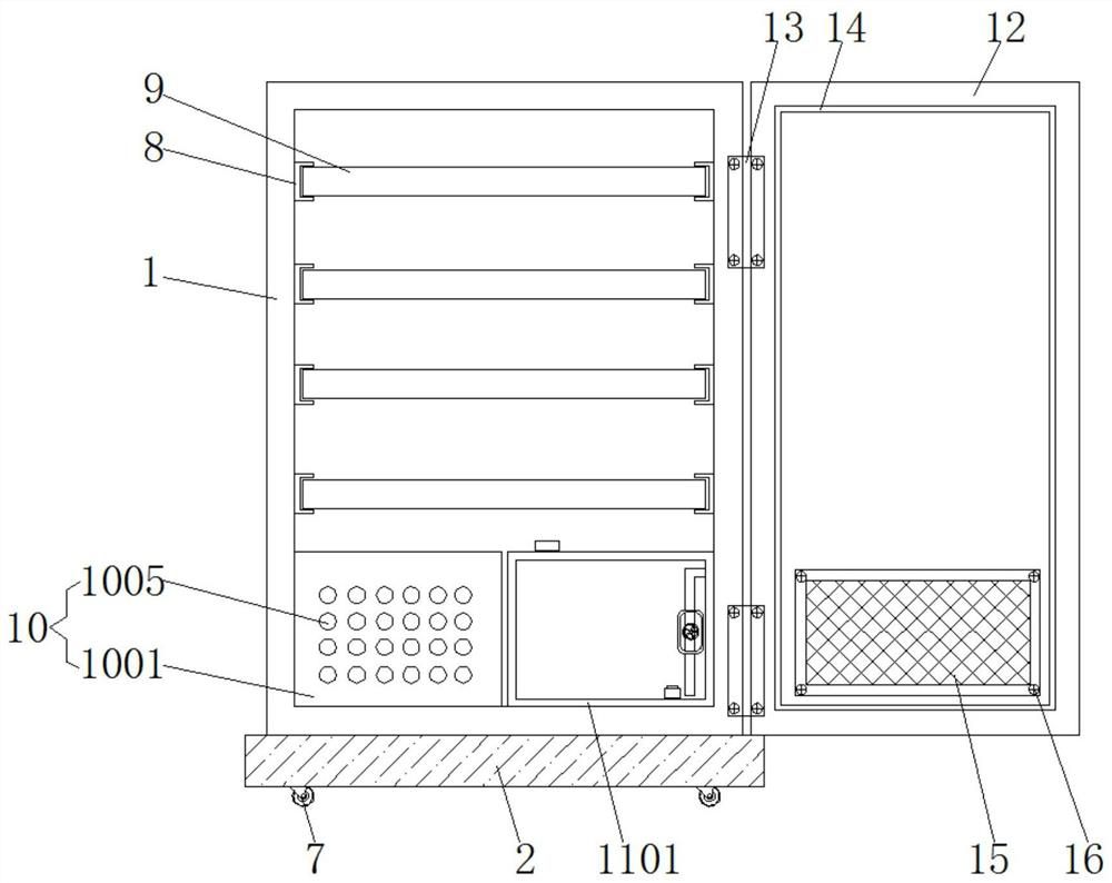
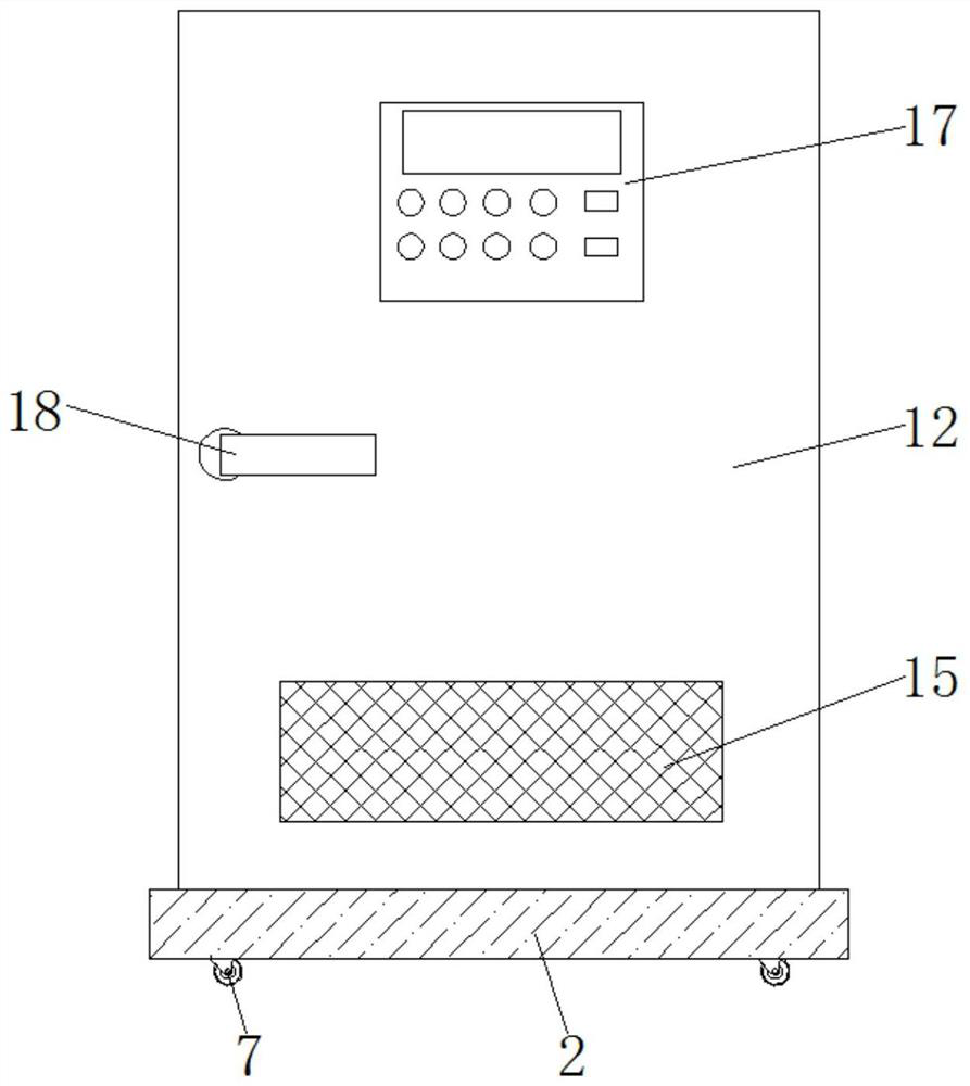
[0031] see Figure 1-6 , the present invention provides a technical solution: an electromagnetic shielding cabinet with shockproof function, according to figure 1 , figure 2 , Figure 4 and Figure 5 As shown, the cabinet main body 1 includes an outer shell 101, an electromagnetic shielding layer 102 and an inner shell 103. The electromagnetic shielding layer 102 is located between the outer shell 101 and the inner shell 103. The electromagnetic shielding ...


PUM


Abstract

The present invention discloses an electromagnetic shielding cabinet with a shockproof function. The cabinet comprises a cabinet main body, a heat dissipation mechanism, a cooling mechanism and a box door, the cabinet main body comprises an outer shell, an electromagnetic shielding layer and an inner shell, a base is installed at the bottom of the outer shell, and an electric telescopic rod is installed in a groove. A plurality of clamping blocks are symmetrically installed on the left side and the right side of the inner wall of the inner shell, the heat dissipation mechanism is installed on the left side of the bottom of the interior of the inner shell, the cooling mechanism is installed on the right side of the bottom of the interior of the inner shell, and sealing strips are arranged at the positions, close to the edges, of the periphery of the inner side of the box door. The electromagnetic shielding cabinet with the shockproof function is provided with the heat dissipation mechanism and the cooling mechanism, and through the arrangement of the motor, the fan blades, the through holes, the air holes, the water inlet pipe, the water pipe, the water pump, the water outlet pipe and the one-way valve, the device can carry out effective heat dissipation and cooling treatment on the electromagnetic shielding cabinet, the heat dissipation efficiency of the electromagnetic shielding cabinet is improved, electrical components in the electromagnetic shielding cabinet are protected, and the service life of the electromagnetic shielding cabinet is prolonged.

Description

technical field [0001] The invention relates to the technical field of cabinets, in particular to an electromagnetic shielding cabinet with an anti-shock function. Background technique [0002] With the gradual deepening of people's awareness of the hazards of electromagnetic leakage and emission of secret-related information systems, various means of preventing electromagnetic leakage and emission have been adopted in the construction of secret-related information networks, including building electromagnetic shielding rooms, laying optical cables and shielding twisted-pair wires. , Use low-radiation equipment, red and black power isolation sockets, shielded cabinets and jammers, etc. Among them, the shielding cabinet has the characteristics of small size, convenient installation and flexible use, and is very suitable for use in those occasions where the electromagnetic shielding room is not suitable for installation and information equipment needs to be protected. [0003]...

Claims


Application Information

Patent Timeline
Patent Type & Authority Applications(China)
IPC IPC(8): H05K9/00H05K5/02H05K5/06H05K7/14H05K7/20
CPCH05K9/0007H05K7/14H05K5/0204H05K7/20272H05K5/06H05K5/069
Inventor 余彐东
Owner 东台市苏宝电磁屏蔽设备有限公司
Why Eureka
Try Eureka