
Self-adaptive brush assembly and door leaf full-automatic dust removal system comprising same

A dust removal system and self-adaptive technology, applied in the direction of dust removal, cleaning methods using tools, cleaning methods using gas flow, etc., can solve problems such as poor effect, easy to cause dust, and low dust cleaning efficiency

Active Publication Date: 2021-09-14
山东和乐门业有限公司
View PDF11 Cites 0 Cited by
  • Summary
  • Abstract
  • Description
  • Claims
  • Application Information

AI Technical Summary

Problems solved by technology

[0003] The existing cleaning is done manually, including loosening the dust with a brush, blowing the soot and other processes. This kind of cleaning has many shortcomings: the manual labor intensity is high, the cleaning efficiency is low, the effect is not good, and it is easy to cause dust.

Method used


Image

  • Self-adaptive brush assembly and door leaf full-automatic dust removal system comprising same
  • Self-adaptive brush assembly and door leaf full-automatic dust removal system comprising same
  • Self-adaptive brush assembly and door leaf full-automatic dust removal system comprising same

Examples


Embodiment 1

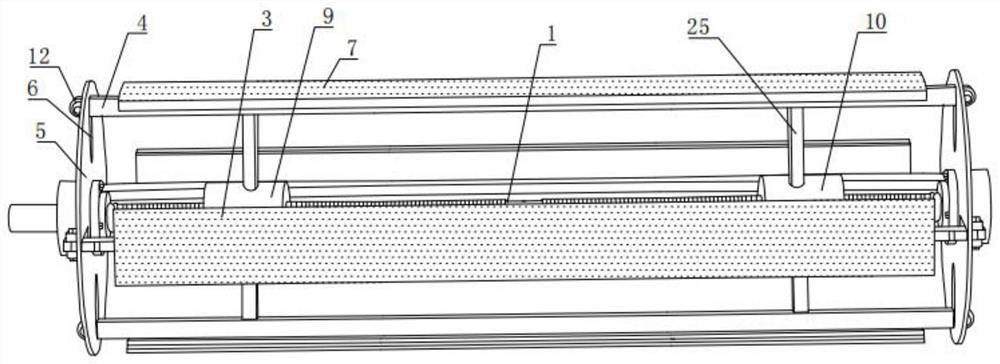
[0035] Such as figure 1 with figure 2 As shown, an adaptive brush assembly includes a lead screw 1, a controller 2, four movable tiles 3, four limit rods 4 and limit circular plates 5 respectively arranged at both ends of the lead screw 1;

[0036] Four limit grooves 6 are evenly distributed on the limit circular plate 5, the end of the limit rod 4 is slidingly fitted with the limit groove 6, and the limit rod 4 is in phase with the movable tile 3. connected, the surface of the movable tile 3 is provided with a brush 7, and a pressure sensor 8 is provided between the brush 7 and the movable tile 3;

[0037] The front section and the rear section of the lead screw 1 are respectively provided with a first helical groove and a second helical groove opposite in direction of rotation, and the front section and the rear section of the lead screw 1 are respectively provided with a first nut seat 9 and a corresponding one. The second nut seat 10; the first nut seat 9 and the second...

Embodiment 2

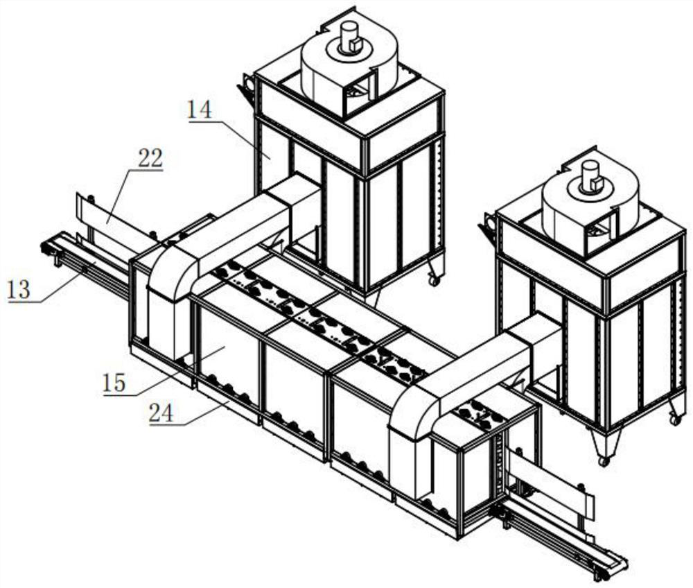
[0046] Such as Figure 1-7 As shown, this embodiment is a fully automatic dust removal system for a door leaf that includes the self-adaptive brush assembly 16 in Embodiment 1, including a feeding mechanism 13, a dust suction mechanism 14 and a plurality of dust removal units 15; the brush assembly 16 has two groups;

[0047] The dust removal unit 15 includes a dust removal box 17, two sets of stoppers 18 and two sets of dust removal air knives 19, the centers of the opposite sides of the dust remover box 17 are respectively provided with openings for door leaves to enter and exit, and each set of stoppers 18 It consists of a plurality of driving wheels 20 arranged along the length direction of the dust removal box 17. Two sets of limiters 18, two sets of brush assemblies 16 and two sets of dust removal air knives 19 are connected to the dust removal box 17 respectively. Limiting parts 18, two groups of brush assemblies 16 and two groups of dedusting air knives 19 are arrange...


PUM


Abstract

The invention discloses a self-adaptive brush assembly which comprises a lead screw, a controller, four movable pads, four limiting rods and limiting circular plates arranged at the two ends of the lead screw correspondingly; four limiting grooves are evenly distributed in each limiting circular plate, the ends of the limiting rods are in sliding fit with the limiting grooves, the limiting rods are connected with the movable pads, brushes are arranged on the surfaces of the movable pads, and pressure sensors are arranged between the brushes and the movable pads; and the invention further discloses a door leaf full-automatic dust removal system comprising the self-adaptive brush assembly. The door leaf full-automatic dust removal system comprises a feeding mechanism, a dust suction mechanism and a plurality of dust removal units. The number of the brush assemblies is two. According to the dust removal system, full-automatic dust removal is achieved, manual work is replaced, the dust removal efficiency is high, dust generated during dust removal is located in a dust removal box, and dust raising is avoided.

Description

technical field [0001] The invention relates to the technical field of door production equipment, in particular to an adaptive brush assembly and a door leaf automatic dust removal system including the assembly. Background technique [0002] Door production mainly involves seven sections, which are sheet metal, phosphating, gluing, plastic spraying, transfer printing, varnishing, and assembly. The workshops involved mainly include three workshops, namely sheet metal workshop, surface workshop, Assembly workshop. In the manufacture of the door leaf, after the door leaf has completed all the manufacturing processes, it needs to be cleaned and then painted or coated. [0003] The existing cleaning is done manually, including loosening the dust with a brush and blowing the soot. This kind of cleaning has many disadvantages: manual labor intensity is high, the cleaning efficiency is low, the effect is not good, and it is easy to cause dust. Contents of the invention [0004] ...

Claims


Application Information

Patent Timeline
IPC IPC(8): B08B1/00B08B1/04B08B5/04B08B15/04B01D46/02
CPCB08B5/04B08B15/04B01D46/02B01D2258/02B08B1/12B08B1/32
Inventor 王红王文娜杨先桃
Owner 山东和乐门业有限公司
Learn More