Interventional therapy auxiliary device for cardiovascular department
A technology for interventional therapy and auxiliary devices, applied in the field of medical devices, can solve the problems of manual adjustment, inconvenience of height adjustment, etc., and achieve the effects of reducing work intensity, good protection effect, and wide application range
- Summary
- Abstract
- Description
- Claims
- Application Information
AI Technical Summary
Problems solved by technology
Method used
Image
Examples
Embodiment 1
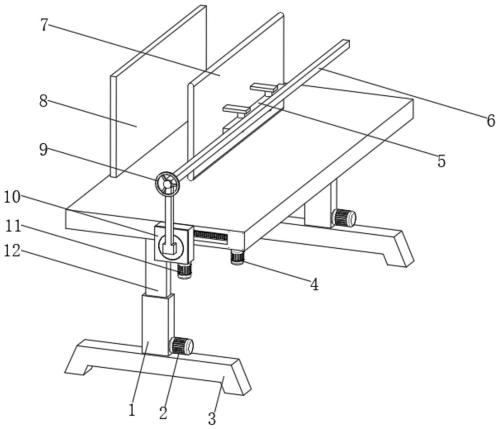
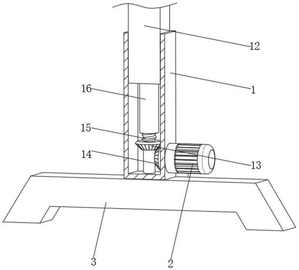
[0028] see figure 1 and 2 , an auxiliary device for cardiovascular interventional therapy, comprising a base 3, the top of the base 3 is fixedly connected with a fixed rod 1, the bottom side of the fixed rod 1 is fixedly connected with a first motor 2, and the top output shaft of the first motor 2 is The first bevel gear 14 is fixedly connected, the inner bottom of the fixed rod 1 is movably connected with the first threaded rod 15, one end of the first threaded rod 15 is fixedly connected with the second bevel gear 13, and the top of the fixed rod 1 is provided with a telescopic rod 12. The bottom end of the telescopic rod 12 is fixedly connected with a pull rod 16, and the first threaded rod 15 is connected with the telescopic rod 12 through the transmission rod of the pull rod 16.
[0029] In this embodiment, by setting the telescopic rod 12 structure at one end of the fixed rod 1, the first motor 2 is operated, and the first motor 2 drives the first bevel gear 14 to rotat...
Embodiment 2
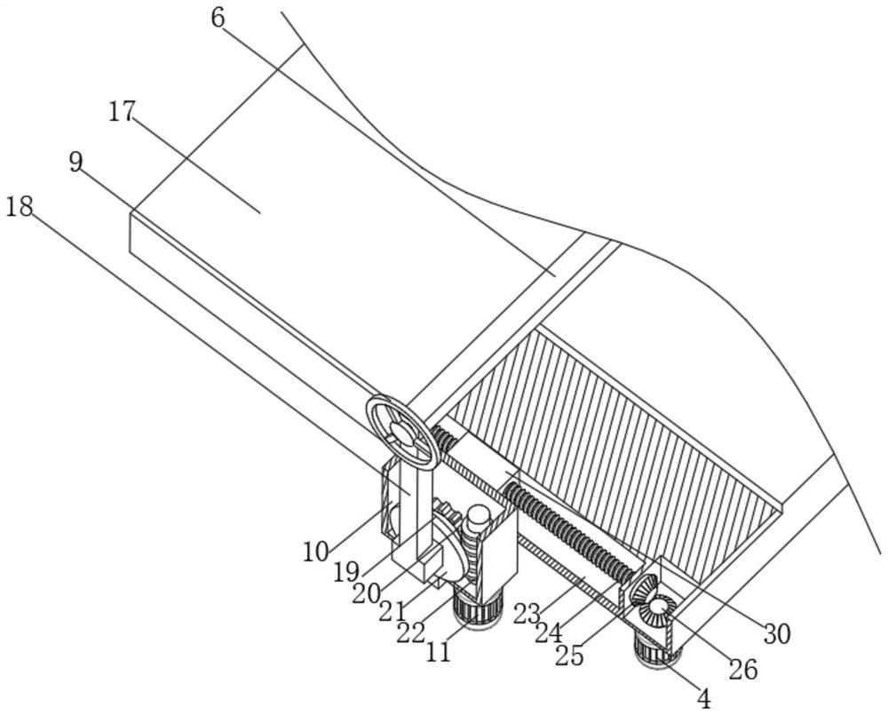
[0031] see figure 1 and 3 , the present embodiment is further optimized on the basis of Embodiment 1, specifically, the top end of the telescopic rod 12 is fixedly connected with a workbench 17, and the top side of the workbench 17 is fixedly connected with a first protective plate 8, and the working One end of the table 17 is provided with a movable slot 23 .
[0032] Specifically, the inside of the movable groove 23 is movably connected with a second threaded rod 24, and one end of the second threaded rod 24 is fixedly connected with the third bevel gear 25, and one end of the bottom of the workbench 17 is fixedly connected with the second motor 4, and the second motor The top output shaft of 4 is fixedly connected with the fourth bevel gear 26, and the second threaded rod 24 is connected with the fourth bevel gear 26 through the third bevel gear 25.
[0033] Specifically, one end of the second threaded rod 24 is movably connected with a mounting block 30, one side of the ...
Embodiment 3
[0036] see figure 1 and 4 , the present embodiment is optimized as follows on the basis of example 1 or example 2, specifically, the top of the mounting rod 18 is fixedly connected with the movable frame 6, and the inside of the movable frame 6 is fixedly connected with the third threaded rod 29.
[0037] Specifically, one end of the third threaded rod 29 is fixedly connected to the rocker 9 , and the other end of the third threaded rod 29 is movably connected to the installation frame 5 .
[0038] Specifically, one side of the installation frame 5 is provided with a second protective plate 7, and one side of the second protective plate 7 is fixedly connected with a connecting plate 27, and one side of the connecting plate 27 is fixedly connected with a mounting bolt 28, and the connecting plate 27 is connected with the installation The frame 5 is fixedly connected by mounting bolts 28 .
[0039]In this embodiment, by setting the structure of the mounting bracket 5 inside th...
PUM
 Abstract
Description
Claims
Application Information
 - R&D
- Intellectual Property
- Life Sciences
- Materials
- Tech Scout
- Unparalleled Data Quality
- Higher Quality Content
- 60% Fewer Hallucinations
Browse by: Latest US Patents, China's latest patents, Technical Efficacy Thesaurus, Application Domain, Technology Topic, Popular Technical Reports.
© 2025 PatSnap. All rights reserved.Legal|Privacy policy|Modern Slavery Act Transparency Statement|Sitemap|About US| Contact US: help@patsnap.com


