An automatic trimming device for the leading edge of a fan blade

A technology for fan blades and blade leading edges is applied in the field of automatic trimming equipment for the leading edges of fan blades to achieve the effect of ensuring production quality

Active Publication Date: 2022-07-08
安徽驭风风电设备有限公司
View PDF5 Cites 0 Cited by
  • Summary
  • Abstract
  • Description
  • Claims
  • Application Information

AI Technical Summary

Problems solved by technology

[0005] Aiming at the deficiencies of the prior art, the present invention provides a leading edge automatic repairing device of the fan blade, which overcomes the deficiencies of the prior art, has a reasonable design and a compact structure, and aims to solve the problem that the leading edge of the fan blade is the most suitable place for contacting wind force. The front end, the front edge surface flatness and arc modification of the fan blade after molding

Method used


Image

  • An automatic trimming device for the leading edge of a fan blade
  • An automatic trimming device for the leading edge of a fan blade
  • An automatic trimming device for the leading edge of a fan blade

Examples


Embodiment 1

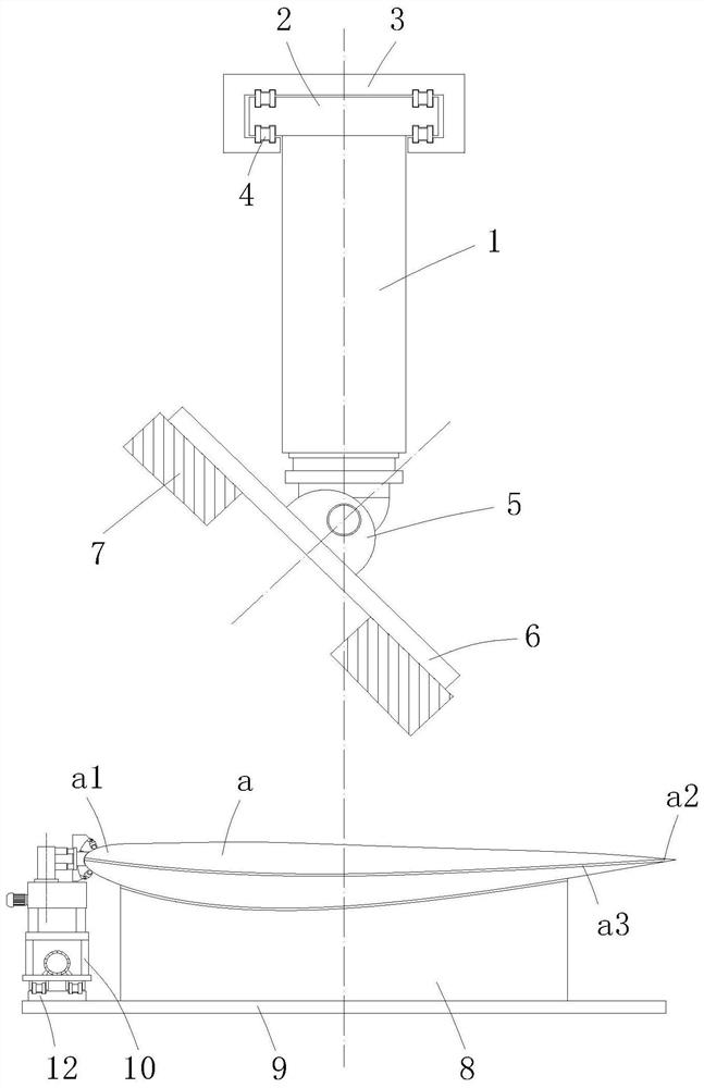
[0030] A device for automatically trimming the leading edge of a fan blade, comprising a support table 8 for laterally supporting the fan blade a and a base 9 for fixing the support table 8 on the ground, above the support table 8 is provided for matching support The table 8 locates the upper positioning unit of the fan blade a, the side of the upper end of the base 9 close to the leading edge a1 of the blade is laid with a trolley track 12, and the trolley track 12 is provided with a leading edge trimming mechanism that can travel autonomously;

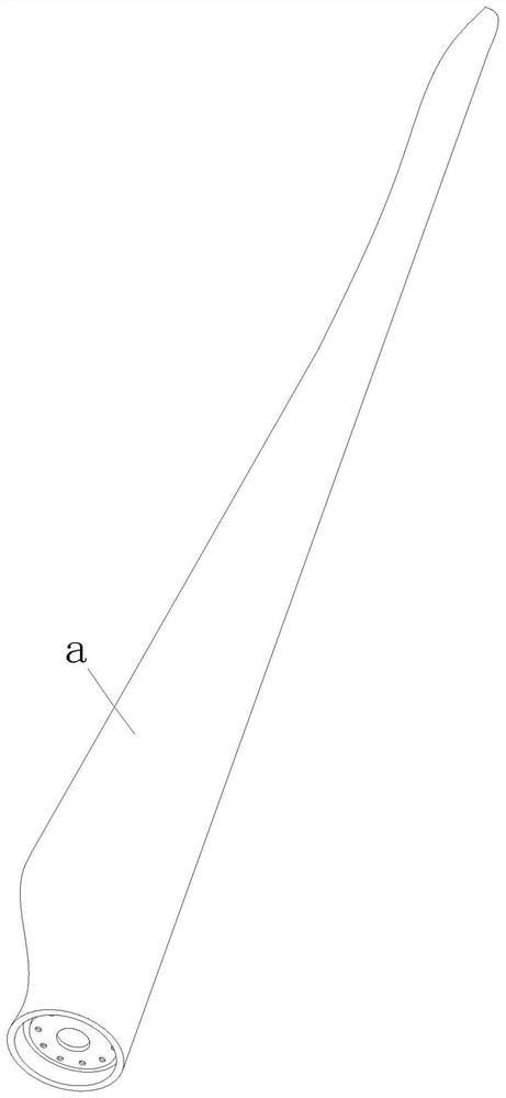
[0031] In this embodiment, as Figure 1-2 As shown, the cross section of the fan blade a shows that the fan blade a includes two sheets and an adhesive layer a3 located between the two sheets and bonding the two sheets. After the fan blade a is bonded and formed, the adhesive layer a3 is The junction layer a3 will protrude on the leading edge a1 and the trailing edge a2 of the fan blade a after the mold is opened. It needs to be modi...

Embodiment 2

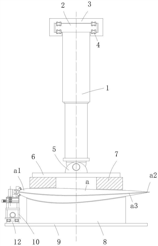
[0039] The difference between this embodiment and Embodiment 1 is that, such as Figure 2-3 As shown, the upper positioning unit includes a lower bag type walking track 3 fixed on the workshop beam, in the walking track 3 is installed a self-propelled moving linear vehicle 2 through the walking wheel 4, and the lower end of the linear traveling vehicle 2 is vertically A lifting cylinder 1 is installed, and the telescopic end of the lifting cylinder 1 is connected to a horizontally arranged mounting table 6 through a rotating seat 5. The lower end of the mounting table 6 is provided with a positioning seat 7 for positioning the fan blade a after matching with the support table 8. The lifting cylinder 1 A pressure sensor II is installed on the telescopic end of the fan blade. Through the walking of the linear traveling vehicle 2 on the walking track 3, it can effectively drive the movement of the positioning seat 7, and match the leading edge automatic trimming mechanism to the s...


PUM


Abstract

The invention relates to the technical field of fan blade manufacturing, and provides an automatic shaping device for the leading edge of the fan blade, aiming at solving the problem that the leading edge of the fan blade is the front end contacting the wind force, the surface flatness and arc of the leading edge after the fan blade is formed The problem of degree modification, including the support table for laterally supporting the fan blades, the upper positioning unit for matching the support table to locate the fan blades is arranged above the support table, and the side of the upper end of the base close to the leading edge of the blade is laid with a trolley track , and the trolley track is provided with a leading edge trimming mechanism; the leading edge automatic trimming mechanism includes a frame body that autonomously travels on the trolley track through the running wheels of the vehicle body, and the frame body is provided with a leading edge trimming mechanism, A leading edge grinding mechanism placed behind the leading edge trimming mechanism and a distance adjusting unit placed under the leading edge trimming mechanism and the leading edge grinding mechanism. The invention is especially suitable for automatic repairing of fan blades, and has high social use value and application prospect.

Description

technical field [0001] The invention relates to the technical field of fan blade manufacturing, in particular to an automatic trimming device for the leading edge of a fan blade. Background technique [0002] Wind energy is a kind of clean and pollution-free renewable energy. It has been used by people for a long time, mainly through windmills to pump water, grind noodles, etc. People are interested in how to use wind to generate electricity. Using wind power to generate electricity is very environmentally friendly, and wind energy It has huge reserves, so it has been paid more and more attention by countries all over the world. [0003] Fan blades are generally more than tens of meters in length, and are mostly made of lightweight composite materials. In normal operation of fans, the speed of the blade tip can reach 60-110m / s. , and the leading edge of the fan blade is the front end contacting the wind force, and the flatness and arc of its surface are related to the aerod...

Claims


Application Information

Patent Timeline
Patent Type & Authority Patents(China)
IPC IPC(8): F03D1/06F03D80/50B24B19/14
CPCF03D1/0675F03D1/0633F03D80/50B24B19/14Y02P70/10
Inventor 岳峰缪金保
Owner 安徽驭风风电设备有限公司
Why Eureka
Try Eureka