Profile measuring machine and movement mechanism

a technology of movement mechanism and measuring machine, which is applied in the direction of mechanical measuring arrangement, measurement device, instruments, etc., can solve the problem of loss of a desired guide function

Active Publication Date: 2020-05-26
MITUTOYO CORP
View PDF25 Cites 0 Cited by
  • Summary
  • Abstract
  • Description
  • Claims
  • Application Information

AI Technical Summary

Benefits of technology

[0015]In the above aspect of the invention, the air pad facing the guide surface guides the second member relative to the first member. Then, the drive roller rolling on the guide surface drives the second member to move relative to the first member. In this movement, the air pad faces the guide region of the guide surface while the drive roller rolls on the drive region of the guide surface, the guide region and the drive region being parallel to each other and not overlapping with each other. Accordingly, even when fine particles of a friction-force-reinforcement material are generated by rolling of the drive roller, the fine particles solely adhere to the drive region, so that adhesion of the fine particles to the guide region is preventable. Consequently, flatness and smoothness of the guide region and the guide function of the air pad can be constantly maintained.
[0017]Since the drive roller is pressed onto the drive region, the first member receives a pressing force from the second member. However, since the air pads provided on both sides of the drive roller in the moving direction prevent generation of unnecessary moment and the like, a posture of the second member can be maintained relative to the first member to keep a proper guide function in the moving direction.
[0019]The profile measuring machine according to the above aspect of the invention may be in a form of a coordinate measuring machine. The table and the column may be in a form of a table and a column of the coordinate measuring machine. For instance, the coordinate measuring machine includes: a cross beam supported by columns; a slider configured to be moved relative to the cross beam; and a Z-spindle configured to be moved up and down relative to the slider. The profile measuring machine according to the above aspect of the invention is applicable to a movement mechanism of each of the slider and the Z-spindle. In comparison, in the movement mechanism of the column and the table, when a portal structure including the column and the Z-spindle is determined as a movable structure, or when the portal structure is fixed and the table is determined as a movable structure, a mass of the movable structure is large, so that the driving force of the drive roller is the maximum. Since the larger driving force increases a generation frequency of fine particles, the profile measuring machine according to the above aspect of the invention is the most effective in the movement mechanism of the column and the table.
[0021]This arrangement determines the drive roller to be positioned above the air pads, so that the driving force generated from the drive roller can act near the centroid of the column and that of the structure including the column, resulting in a favorable moving accuracy. Although there is a possibility that the fine particles of the drive roller may fall onto the guide region from the drive region positioned above the guide region, the fine particles are not pressed onto the guide region by the drive roller but may be removed with air flowing over the guide region from the air pads. Thus, adhesion of the fine particles to the guide region is avoidable.

Problems solved by technology

The adhesion of the fine particles and the like to the guide surface impairs flatness and smoothness of the guide surface, which may hamper an appropriate static pressure floating of the air pads with a small interval, resulting in a loss of a desired guide function.

Method used


Image

  • Profile measuring machine and movement mechanism
  • Profile measuring machine and movement mechanism
  • Profile measuring machine and movement mechanism

Examples


Embodiment Construction

)

[0028]Exemplary embodiment(s) of the invention will be described below with reference to the attached drawings.

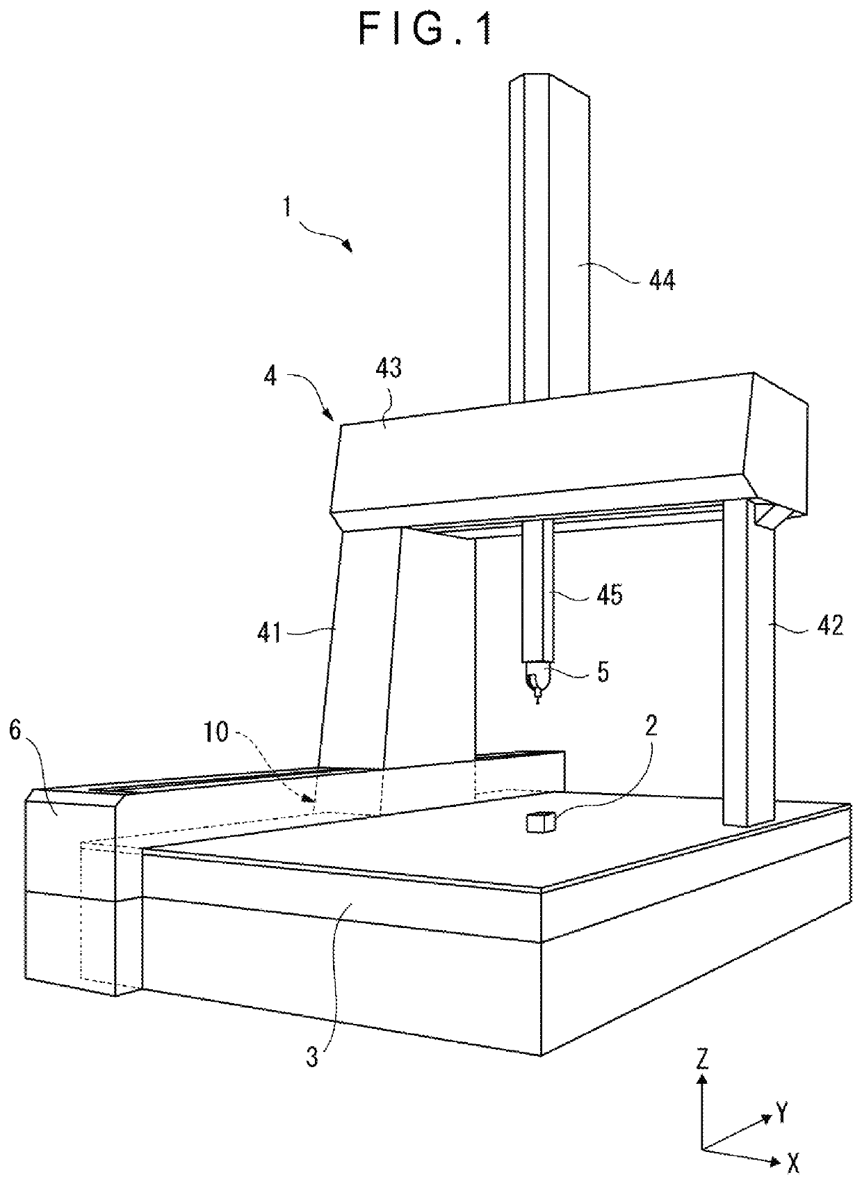
[0029]As shown in FIG. 1, a coordinate measuring machine 1, which is a profile measuring machine according to an exemplary embodiment of the invention, includes a table 3 on which a workpiece 2 is to be placed, and a portal structure 4 straddling the table 3. A measurement probe 5 is attached to the structure 4 and is movable by the structure 4 in three dimensions relative to the workpiece 2.

[0030]The portal structure 4 includes: a pair of columns 41, 42 provided to both sides of the table 3; a beam 43 bridging the columns 41, 42 and extending in an X-axis direction; and a slider 44 movable along the beam 43. A Z-spindle 45 is supported by the slider 44. A measurement probe 5 is attached to a lower end of the Z-spindle 45.

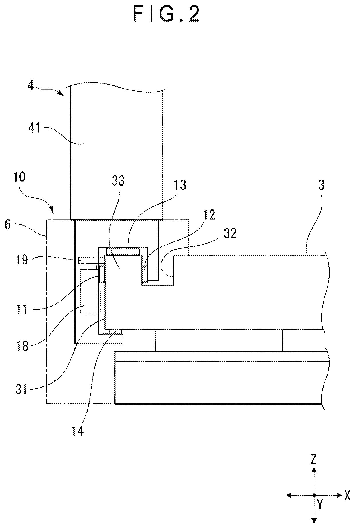
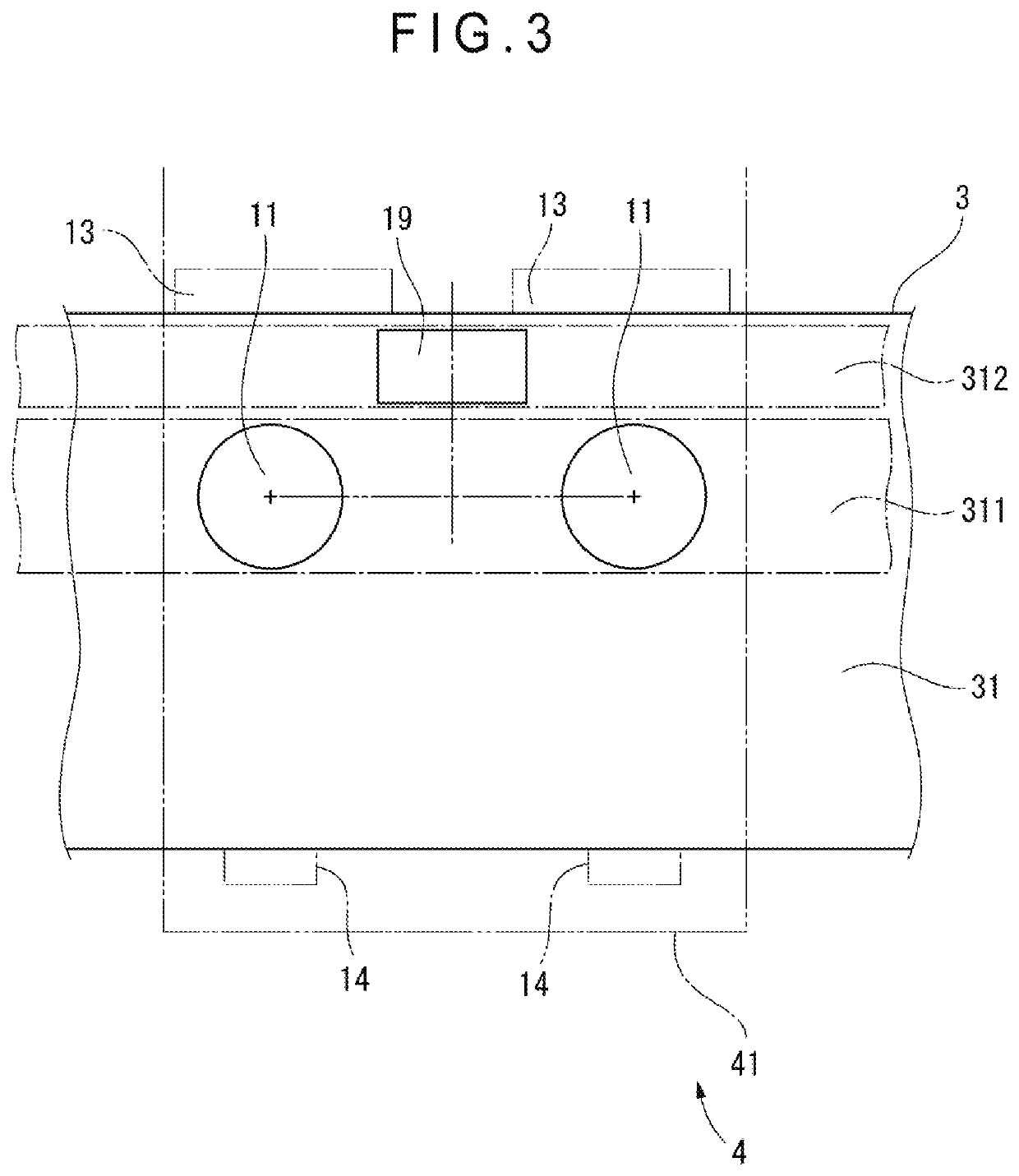
[0031]An X-axis movement mechanism (not shown) provided between the beam 43 and the slider 44, whereby the slider 44 is movable in the X-axis direction a...


PUM


Abstract

A coordinate measuring machine includes: a table and a column which are configured to relatively move in a predetermined moving direction; a guide surface formed on the table and having a guide region and a drive region extending in the moving direction in parallel to each other; at least one air pad formed to the column and facing the guide region; and a drive roller formed to the column and rolling on the drive region.

Description

[0001]The entire disclosure of Japanese Patent Application No. 2017-001270 filed Jan. 6, 2017 is expressly incorporated by reference herein.TECHNICAL FIELD[0002]The present invention relates to a profile measuring machine and a movement mechanism.BACKGROUND ART[0003]A coordinate measuring machine configured to move a probe in three dimensions with respect to a workpiece (measurement target) has been known as a profile measuring machine. A portal movement mechanism straddling the workpiece is used in a large-sized coordinate measuring machine (see Patent Literature 1: JP2010-122118A).[0004]The portal coordinate measuring machine includes: a table on which the workpiece is placed; a pair of columns provided on both sides of the table; a beam bridging the pair of columns and extending in an X-axis direction; a slider capable of moving on and along the beam; a Z-spindle configured to be moved up and down relative to the slider; and a probe attached to a lower end of the Z-spindle. The c...

Claims


Application Information

Patent Timeline
Patent Type & Authority Patents(United States)
IPC IPC(8): G01B5/008G01B5/20
CPCG01B5/20G01B5/008
Inventor SAKAMOTO, MASAHIROOOYAMA, YOSHIKAZUTAKIZAWA, MASATOTAKESAKO, KOJI
Owner MITUTOYO CORP
Why Eureka
Try Eureka