
Intelligent valve and using method thereof

A smart valve, smart valve technology, applied in the direction of liquid cleaning methods, cleaning methods and utensils, chemical instruments and methods, etc., can solve the problems of reducing service life, reducing the sealing effect of smart valves, damage, etc.

Inactive Publication Date: 2021-09-14
JIANGSU INTELLIGENT SPECIAL VALVE CO LTD
View PDF5 Cites 0 Cited by
  • Summary
  • Abstract
  • Description
  • Claims
  • Application Information

AI Technical Summary

Problems solved by technology

In the prior art, the smart valve mainly controls the position of the spool to stop the flow of the fluid. However, during the long-term use of the smart valve, the sealing position of the spool will absorb or condense some impurities in the fluid. Cleaning it is easy to cause damage to it, thereby reducing the sealing effect of the smart valve and reducing its service life

Method used


Image

  • Intelligent valve and using method thereof
  • Intelligent valve and using method thereof
  • Intelligent valve and using method thereof

Examples


Embodiment 1

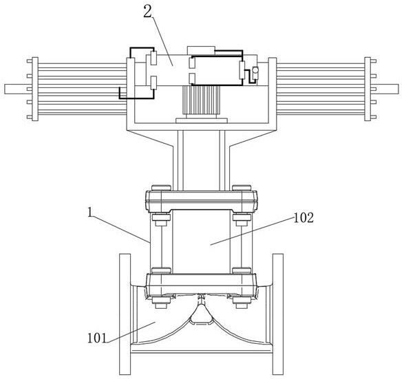
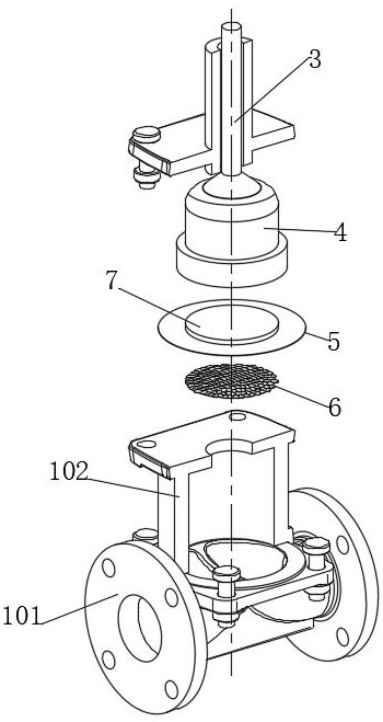
[0053] see Figure 1-10 , an intelligent valve, comprising an intelligent valve body 1 and an intelligent valve controller 2 fixedly installed on the upper end of the intelligent valve body 1, the intelligent valve body 1 includes an intelligent valve body 101, and the upper end of the intelligent valve body 101 is fixedly connected with a Smart bonnet 102, the smart bonnet 102 is slidingly connected with the magnetic push valve stem 3 electrically connected to the smart valve controller 2, please refer to image 3 , the lower end of the magnetic push valve rod 3 is fixedly connected with the regulating valve core 4, and the temperature-controlled flexible seal 5 matching the intelligent valve body 101 is arranged between the intelligent valve body 101 and the intelligent valve cover 102, and the temperature-controlled flexible seal The 5 lower end is connected with self-cleaning fish scale group 6; Please refer to Figure 4-7 The self-cleaning fish scale group 6 includes a t...

Embodiment 2

[0057] see Figure 1-10 , where the same or corresponding components as those in Embodiment 1 use the corresponding reference numerals as in Embodiment 1, and for the sake of simplicity, only the differences from Embodiment 1 will be described below. The difference between this embodiment 2 and embodiment 1 is: please refer to figure 1 with image 3 The upper end of the temperature-controlled flexible seal 5 is fixedly connected with the pressurized thermal expansion sheet 7 , and the lower end of the regulating valve core 4 is provided with a flexible core groove 401 , and the flexible core groove 401 is fixedly connected with the pressurized thermal expansion sheet 7 . see Figure 4A booster sliding hole 402 is opened in the regulating valve core 4, and a magnetic push type wall heat column 8 matched with the booster thermal expansion sheet 7 is slidably connected to the booster sliding hole 402. When the temperature-controlled flexible seal 5 closes the smart valve body ...

Embodiment 3

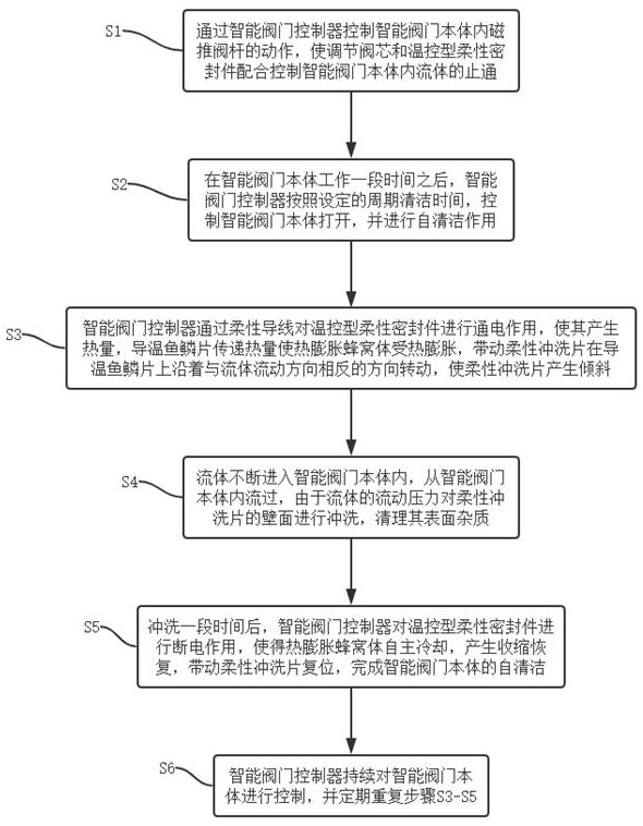
[0060] see Figure 1-10 , where the same or corresponding components as those in Embodiment 1 use the corresponding reference numerals as in Embodiment 1, and for the sake of simplicity, only the differences from Embodiment 1 will be described below. The difference between this embodiment 3 and embodiment 1 is: please refer to figure 2 , a method for using an intelligent valve, comprising the steps of:

[0061] S1. Control the action of the magnetic push valve rod 3 in the smart valve body 1 through the smart valve controller 2, so that the regulating valve core 4 and the temperature-controlled flexible seal 5 cooperate to control the flow of the fluid in the smart valve body 1;

[0062] S2. After the smart valve body 1 works for a period of time, the smart valve controller 2 controls the smart valve body 1 to open according to the set cycle cleaning time (see Figure 8 ), and self-cleaning effect;

[0063] S3. The intelligent valve controller 2 energizes the temperature-c...


PUM


Abstract

The invention discloses an intelligent valve and a using method thereof, and belongs to the field of intelligent valves. The intelligent valve comprises an intelligent valve body and an intelligent valve controller fixedly installed at the upper end of the intelligent valve body, and a temperature control type flexible sealing piece matched with the intelligent valve body is arranged between the intelligent valve body and an intelligent valve deck; a self-cleaning fish scale set is connected with the lower end of the temperature control type flexible sealing piece, the self-cleaning fish scale set can be washed through the matching effect of the temperature control type flexible sealing piece and the self-cleaning fish scale set by means of fluid pressure, residues of impurities on the wall face of the self-cleaning fish scale set are reduced, damage of the impurities to the temperature control type flexible sealing piece is reduced, the sealing effect of the intelligent valve body is improved, and the service life of the intelligent valve body is prolonged; and the self-cleaning effect is achieved through flowing resistance, the control difficulty of an intelligent valve controller is reduced, the manufacturing cost of the intelligent valve body is reduced, and the economic benefits of the intelligent valve body are improved.

Description

technical field [0001] The invention relates to the field of intelligent valves, and more specifically, relates to an intelligent valve and its usage method. Background technique [0002] Valves are pipeline accessories used to open and close pipelines, control flow direction, adjust and control the parameters (temperature, pressure and flow) of the conveying medium. According to its function, it can be divided into shut-off valve, check valve, regulating valve and so on. The valve is a control component in the fluid delivery system, which has functions such as cut-off, adjustment, flow diversion, reverse flow prevention, pressure stabilization, flow diversion or overflow pressure relief. Valves used in fluid control systems range from the simplest cut-off valves to various valves used in extremely complex automatic control systems, with a wide variety of varieties and specifications. [0003] The intelligent valve is a valve with powerful computing power installed in the ...

Claims


Application Information

Patent Timeline
Patent Type & Authority Applications(China)
IPC IPC(8): F16K7/12F16K31/06F16K49/00B08B3/10B08B13/00
CPCF16K7/126F16K31/0672F16K49/002B08B3/10B08B13/00
Inventor 方文玲
Owner JIANGSU INTELLIGENT SPECIAL VALVE CO LTD
Learn More