Multifunctional pilot operated safety valve

A pilot-operated safety valve, multi-functional technology, applied in the field of multi-functional pilot-operated safety valve, can solve problems such as the impact of the surrounding environment

Active Publication Date: 2021-09-14
四川长仪油气集输设备股份有限公司
View PDF22 Cites 0 Cited by
  • Summary
  • Abstract
  • Description
  • Claims
  • Application Information

AI Technical Summary

Problems solved by technology

[0006] In order to overcome the defects and deficiencies in the above-mentioned prior art, the present invention provides a multifunctional pilot safety valve. When it is necessary to discharge a certain amount of medium it transports, it will affect the surrounding environment

Method used


Image

  • Multifunctional pilot operated safety valve
  • Multifunctional pilot operated safety valve
  • Multifunctional pilot operated safety valve

Examples


Embodiment 1

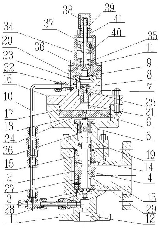
[0032] As a preferred embodiment of the present invention, with reference to the attached figure 1 , figure 2 with image 3 As shown, this embodiment discloses a multifunctional pilot-operated safety valve, including a main valve part and a pilot valve part, and the main valve part and the pilot valve part are assembled into one; more specifically, as figure 1 As shown, it includes valve body 1, main valve sleeve 2, main valve core 3, valve stem 4, cylinder body 5, main valve piston 6, pilot valve seat 7, pilot valve disc 8, piston shaft 9, A medium inlet 12 and a medium outlet 13 are arranged on the pressure guiding pipe 10 and the pilot valve adjustment assembly 11 , and the valve body 1 .

[0033] Such as figure 2 As shown, the main valve sleeve 2 is pressed and assembled in the valve body 1 by the cylinder body 5, and the cylinder body 5 and the valve body 1 are fixedly assembled together; The spring chamber 15 of the spring 14; the cylinder body 5 is equipped with a...

Embodiment 2

[0039] As yet another preferred embodiment of the present invention, this embodiment is a specific implementation manner further improved on the basis of Embodiment 1, specifically as follows:

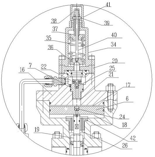
[0040] refer to image 3 As shown, as an implementation of this embodiment, the passage through which the disc chamber 22 on the pilot valve seat 7 communicates with the piston upper chamber 17 is a damping passage. The damping passage on the pilot valve seat 7 further improves the opening sensitivity and precision of the main valve.

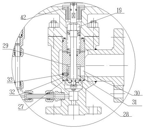
[0041] As another implementation of this embodiment, the end of the cylinder body 5 connected to the valve body 1 is provided with a channel hole II26, and the channel hole II26 is connected to the cavity on the main valve sleeve 2 in the valve body 1. Correspondingly, after the cylinder body 5 is assembled on the valve body 1 , the passage hole II 26 on the cylinder body 5 and the cavity on the main valve sleeve 2 form the spring chamber 15 . The pass...

Embodiment 3

[0043] As yet another preferred embodiment of the present invention, this embodiment is a specific implementation manner further improved on the basis of embodiment 1 and / or embodiment 2, specifically as follows:

[0044] As an implementation of this embodiment, the main valve spool 3 includes an upper spool 27 and a lower spool 28, the lower spool 28 is connected to the bottom of the upper spool 27, and the upper spool 27 is connected to the valve stem 4, And the upper spool 27 is embedded in the main valve sleeve 2 for installation, the lower end of the main valve sleeve 2 is provided with a spool cavity 29 for the upper spool 27 to nest, and the side wall of the spool cavity 29 is provided with a valve that communicates with the main valve medium outlet 13. The fenestration of 30. The split structure setting of the upper spool 27 and the lower spool 28 is equivalent to setting double seals. If there is a problem with the sealing pair between the lower spool 28 and the botto...


PUM


Abstract

The invention discloses a multifunctional pilot operated safety valve, and relates to the technical field of valves. According to the multifunctional pilot operated safety valve, a pilot valve and a main valve are designed to be of an integrated structure, a diaphragm type structure in an existing pilot operated safety valve is omitted, a main valve piston is arranged, a valve rod of the main valve is connected with the main valve piston, a damping hole is formed in the main valve piston, and after the pilot valve completes control over the main valve, gas in the pilot valve can be delivered out from the rear end of the main valve and cannot be discharged outwards, so that the environment is not influenced. According to the multifunctional pilot operated safety valve, no media are discharged outwards during take-off and release, and the function of safely discharging gas, liquid and high-back-pressure media at the same time is achieved. The valve has the advantages of being accurate in take-off pressure, high in discharge precision, sensitive in action, reliable in sealing, capable of meeting high-back-pressure discharge, long in service life and the like.

Description

technical field [0001] The invention relates to the technical field of valves, in particular to the technical field of safety valves for transmission and distribution pipelines, and more specifically to a multifunctional pilot-operated safety valve. Background technique [0002] With the rapid development of my country's economy, various high-pressure gases are widely used in industry and civil use, such as long-distance pipeline distribution of natural gas and regional gas supply. The overpressure caused by various reasons leads to the failure of the pipeline or container carrying the high-pressure gas, and the gas in the pipeline is suddenly released due to high compression to generate shock waves, causing devastating damage to nearby residents or buildings. In view of this, most of the control methods for such incidents at home and abroad are to adopt the method of limiting overpressure release, that is, safe pressure release. [0003] The traditional safety valve is of ...

Claims


Application Information

Patent Timeline
IPC IPC(8): F16K31/363F16K17/10
CPCF16K31/363F16K17/10
Inventor 王元清陈林云周斌
Owner 四川长仪油气集输设备股份有限公司
Why Eureka
Try Eureka