
A catheter fixing device with adjustable spatial position

A catheter fixing and spatial position technology, which is applied in air transportation, pipe support, sustainable transportation, etc., can solve the problems that the catheter fixing clamp cannot be adjusted in space, cannot be easily installed according to the design drawings, and the catheter has large processing tolerances, etc., to achieve The effect of avoiding the risk of damage, good interchangeability and maintainability, and saving installation time

Active Publication Date: 2022-06-03
中国航发贵阳发动机设计研究所
View PDF19 Cites 0 Cited by
  • Summary
  • Abstract
  • Description
  • Claims
  • Application Information

AI Technical Summary

Problems solved by technology

[0003] The processing of the duct has a large processing tolerance, so the physical tube shape of the duct is quite different from the designed tube shape. When the tube is assembled on the engine, it is often impossible to install it easily according to the design drawing, and there is a large assembly stress. Therefore, it is necessary to Tube type correction is applied to the conduit, but there is also a certain level of assembly stress in the corrected conduit
[0004] At present, the conduit is fixed on the section or accessories of the engine casing through clamps and brackets. Adjusting the span of the conduit through the clamps and brackets is a conventional method for adjusting and optimizing the dynamic frequency and stress of the conduit. The existing conduit fixing clamps cannot Spatial adjustment according to conduit tube type to meet stress-free or small-stress assembly

Method used


Image

  • A catheter fixing device with adjustable spatial position
  • A catheter fixing device with adjustable spatial position
  • A catheter fixing device with adjustable spatial position

Examples


Embodiment 1

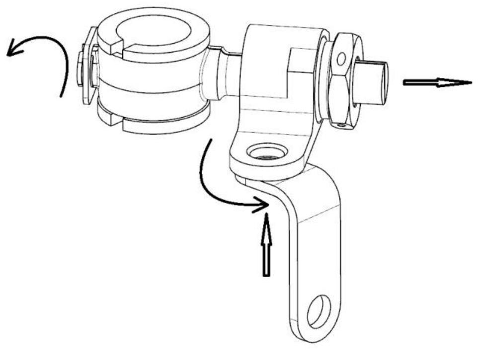
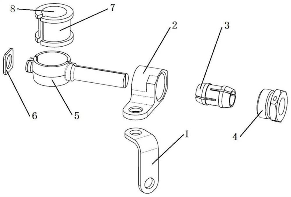
[0029] like Figures 1 to 8 The shown catheter fixing device with adjustable space position includes a bracket I1 and a clamp 5; the clamp 5 is composed of upper and lower halves, and one end of the clamp 5 is provided with a clamp mouth with a clamp slot. The end 18, the other end is connected with a clamp long handle 19; one side of the clamp small mouth end 18 is provided with a clamp small mouth end cylinder 21 with a clamp small mouth end retaining ring 20, and the other side is provided with a clamp small mouth end cylinder 21. The small mouth end of the clamp is chamfered 22, and the small mouth end cylinder 21 of the clamp is sleeved with a clamp ring 6; the clamp long handle 19 is sleeved with a clamp bracket 2, an elastic clamp ring 3, a nut 4, and a clamp The hoop bracket 2 and the elastic snap ring 3 are connected with the hoop long handle 19 through the nut 4, and the hoop bracket 2 is connected with the bracket I1; The tapered surface 13 and the elastic snap rin...

Embodiment 2

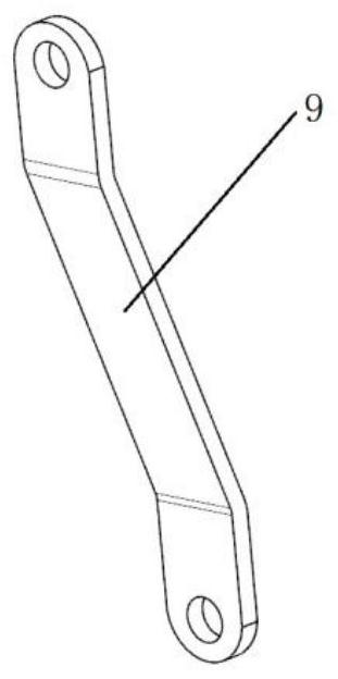
[0032] The solution of Example 1 is adopted, and: the bracket I1 can be replaced with a bracket II9 or a bracket III10. When the bracket I1 is used, the clamp bracket 2 is vertically connected to the bracket I1, and when the bracket II9 is ​​used, the clamp bracket 2 and the bracket II9 is ​​connected horizontally. When the bracket III10 is used, the clamp bracket 2 is connected to the bracket I1 through a threaded rod 11, and the threaded rod 11 is provided at one end of the bracket III10.

Embodiment 3

[0034] The solution of Embodiment 1 is adopted, and the elastic snap ring 3 is sleeved between the clamp bracket 2 and the nut 4, and is made of elastically deformable material.


PUM


Abstract

The invention provides a catheter fixing device with adjustable spatial position, which includes a bracket I and a clip; the clip is composed of upper and lower halves, and one end of the clip is provided with a small mouth end of the clip with a clip groove. The other end is connected with a long handle of the clamp; one side of the small mouth end of the clamp is provided with a small mouth end cylinder of the clamp with a retaining ring at the small mouth end of the clamp, and the other side is provided with a chamfer at the small mouth end of the clamp, A collar is sleeved on the cylinder at the small mouth end of the clamp. The present invention can be adjusted in the direction of two degrees of freedom in space, adapting to a variety of assembly positions; in view of the inconsistency between the physical tube shape and the designed tube shape of the catheter, it can avoid the tube shape correction of the catheter and install it directly, saving installation time and avoiding the The risk of damage caused by the shape correction; the assembly stress of the catheter to the bracket is reduced, the stress level of the bracket is reduced, and the service life is prolonged; a variety of components have good interchangeability and maintainability.

Description

technical field [0001] The invention relates to a duct fixing device with adjustable spatial position, belonging to the technical field of aero-engine pipeline fixing. Background technique [0002] Aero-engine and gas turbine ducts are important connecting parts that connect accessories and engine chambers to realize the normal functioning of the engine in order to meet the realization of specific functions such as air cooling, supercharging, bearing lubrication, combustion chamber oil supply and main pump control. [0003] The machining of the conduit has a large machining tolerance, so the actual tube type of the conduit is quite different from the design tube type. When the conduit is assembled on the engine, it is often impossible to easily install it according to the design drawings, and there is a large assembly stress. Therefore, it is necessary to The conduit is cast corrected, but the corrected conduit also has a certain level of assembly stress. [0004] At presen...

Claims


Application Information

Patent Timeline
Patent Type & Authority Patents(China)
IPC IPC(8): F16L3/16F16L3/12F16L3/237
CPCF16L3/16F16L3/12F16L3/237Y02T50/60
Inventor 刘鹏飞潘海谢忠焰冉勇王达喜肖建平
Owner 中国航发贵阳发动机设计研究所
Learn More