PCB fixing device facilitating PCB detection

A technology for PCB boards and fixing devices, which is applied in the direction of measuring devices, instruments, scientific instruments, etc., and can solve problems such as errors in test results and easy deviation of PCB board positions

Pending Publication Date: 2021-09-14
深圳市晶三力电子有限公司
View PDF6 Cites 1 Cited by
  • Summary
  • Abstract
  • Description
  • Claims
  • Application Information

AI Technical Summary

Problems solved by technology

[0005] In order to overcome the shortcomings of manually placing the PCB board on the table and using the instrument to make the position of the PCB board shift easily during the detection, and the use of the instrument to detect is affected by the external light source, which may easily lead to e

Method used


Image

  • PCB fixing device facilitating PCB detection
  • PCB fixing device facilitating PCB detection
  • PCB fixing device facilitating PCB detection

Examples


Embodiment 1

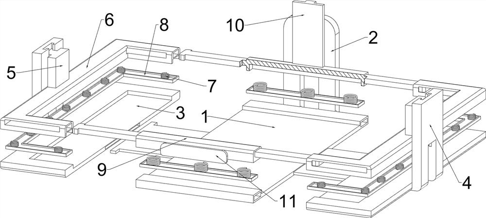
[0036] like figure 1 , figure 2 and image 3 As shown, a PCB board fixing device that is convenient for PCB board detection includes a placement board 1, a limiting board 2, a moving board 3, a limiting block 4, a slider 5, a pull rod 501, a clamping frame 6, and a first elastic member 7. Splint 8, first connecting rod 9, slide plate 10, baffle plate 11, fixing mechanism 12 and translation mechanism 13, fixing mechanism 12 is provided with translation mechanism 13, and translation mechanism 13 is provided with placing plate 1, after placing plate 1 The limit plate 2 is arranged on the side, and the left and right sides of the placement plate 1 are slidingly provided with the moving plate 3. The two moving plates 3 are provided with the limit block 4 on the opposite side, and the two limit blocks 4 are sliding on the opposite side. A slider 5 is provided, and the tops of the two sliders 5 are provided with pull rods 501, the bottoms of the two sliders 5 are provided with cla...

Embodiment 2

[0039] like figure 1 , figure 2 , image 3 , Figure 4 , Figure 5 , Image 6 and Figure 7 As shown, on the basis of Embodiment 1, the fixing mechanism 12 includes a bottom plate 1201, a support seat 1202, a fixed sleeve 1203, a fan-shaped ring 1204 and a bolt 1205. The top of the bottom plate 1201 is provided with a support seat 1202, and the left and right sides of the support seat 1202 Two fixing sleeves 1203 are provided on each of the four fixing sleeves 1203, and two fan-shaped rings 1204 are arranged on each of the four fixing sleeves 1203. The material of the fan-shaped rings 1204 is rubber, and bolts 1205 are threaded between two similar fan-shaped rings 1204.

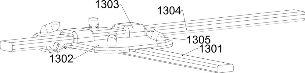
[0040] The translation mechanism 13 includes a first square slide bar 1301, a support plate 1302, a rod cover 1303, a second square slide bar 1304, and a support post 1305. The inside of the support seat 1202 is longitudinally slidably provided with a first square slide bar 1301. A square slide bar 130...

Embodiment 3

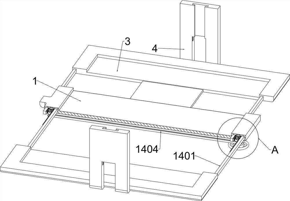
[0043] like figure 1 , Figure 8 , Figure 9 , Figure 10 , Figure 11 , Figure 12 , Figure 13 , Figure 14 and Figure 15 As shown, on the basis of Embodiment 2, a length adjustment mechanism 14 is also included. The length adjustment mechanism 14 includes a rack 1401, a first rotating shaft 1402, a circular gear 1403, a first transmission belt 1404 and a turntable 1405. The two moving The front and rear sides of the board 3 are provided with racks 1401, the bottom of the placement board 1 is provided with a first rotating shaft 1402 in a rotating manner, and the tops of the two first rotating shafts 1402 are rotatably provided with a circular gear 1403, and the circular gears 1403 are connected to The adjacent racks 1401 cooperate, and the lower parts of the two first rotating shafts 1402 are connected with a first transmission belt 1404 through a transmission belt, and the bottom end of the first rotating shaft 1402 on the front side is provided with a turntable 14...


PUM


Abstract

The invention relates to a fixing device and particularly relates to a PCB fixing device facilitating PCB detection. According to the PCB fixing device facilitating PCB detection, an external light source can be shielded, a PCB can be clamped, and the position of the PCB can be conveniently adjusted. The PCB fixing device facilitating PCB detection provided by the invention comprises a fixing mechanism on which a translation mechanism is arranged; a placing plate which is arranged on the translation mechanism; and a limiting plate which is arranged on one side of the placing plate. A clamping plate can clamp a PCB, a worker tightens a fan-shaped ring by twisting a bolt to fix a supporting seat on a frame of an observation instrument, the worker can conveniently use the instrument to detect the PCB, and the worker can enable the PCB to move to a proper position to be detected by pushing a first square sliding rod and a second square sliding rod.

Description

technical field [0001] The invention relates to a fixing device, in particular to a PCB board fixing device which is convenient for PCB board detection. Background technique [0002] PCB inspection typically measures impedance characteristics between test points to detect any continuity. It can be mainly divided into two categories: visual test method and electrical test method. Visual testing determines whether a board is acceptable by visual inspection by an operator using a magnifying glass or a calibrated microscope and determines when corrective action is required. Electrical performance testing is the process of identifying manufacturing defects and testing analog, digital and mixed-signal components to ensure they meet specifications. [0003] The main advantage of the traditional visual test method is that the initial cost is low, but there is no test fixture. When testing the PCB board, it is generally placed on the table manually and the instrument is used to tes...

Claims


Application Information

Patent Timeline
IPC IPC(8): G01N21/01
CPCG01N21/01
Inventor 李璀
Owner 深圳市晶三力电子有限公司
Why Eureka
Try Eureka