Virtual power plant electric energy regulation and control equipment and method

A technology of virtual power plants and electric energy, which is applied in substation/distribution device casings, electrical components, circuit devices, etc., and can solve problems such as insufficient development efforts, affecting normal power consumption of factories, enterprises and residents, and inconvenience

Inactive Publication Date: 2021-09-14
GUANGZHOU POWER SUPPLY BUREAU GUANGDONG POWER GRID CO LTD
View PDF4 Cites 0 Cited by
  • Summary
  • Abstract
  • Description
  • Claims
  • Application Information

AI Technical Summary

Problems solved by technology

[0004] The invention provides a virtual power plant power regulation device and method, which can switch the power supply in time according to the needs, and can transfer energy from some high-intensity power supply regions to regions with small power supply demand according to the different power supply capabilities of the regions , the advantage of improving the use effect of the power plant solves the problem that the existing virtual power plant is not developed enough in the process of use, which leads to the inability to replace the power supply source of the equipment in time according to the different regions or power supply capabilities in the process of energy conversion, which leads to The power supply capacity in some areas is insufficient, and personnel are required to maintain for a long time, which has caused some inconvenience, and when the existing equipment is in use, when the power transformer equipment in the area fails, the area will cause a power outage , problems that affect the normal electricity consumption of factories, enterprises and residents

Method used


Image

  • Virtual power plant electric energy regulation and control equipment and method
  • Virtual power plant electric energy regulation and control equipment and method
  • Virtual power plant electric energy regulation and control equipment and method

Examples


Embodiment Construction

[0019] The following will clearly and completely describe the technical solutions in the embodiments of the present invention with reference to the accompanying drawings in the embodiments of the present invention. Obviously, the described embodiments are only some, not all, embodiments of the present invention. Based on the embodiments of the present invention, all other embodiments obtained by persons of ordinary skill in the art without making creative efforts belong to the protection scope of the present invention.

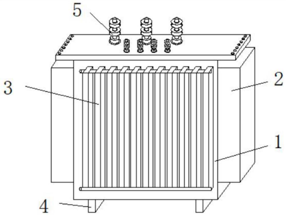
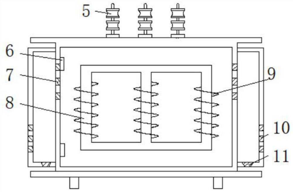
[0020] see Figure 1-3 , a virtual power plant electric energy control equipment and method, comprising a deployment device body 1, an insulating block 5 is fixedly installed on the top of the deployment device body 1, a heat dissipation bellows 2 are fixedly installed on both sides of the deployment device body 1, and the front of the deployment device body 1 A cooling fin 3 is fixedly installed, a base 4 is fixedly installed on the bottom of the blending dev...


PUM


Abstract

The invention relates to the technical field of virtual power plants, and discloses virtual power plant electric energy regulation and control equipment and method. The virtual power plant electric energy regulation and control equipment comprises an allocation device body, an insulation block is fixedly installed at the top of the allocation device body, heat dissipation air boxes are fixedly installed on the two sides of the allocation device body, and heat dissipation fins are fixedly installed on the front face of the allocation device body; and a base is fixedly installed at the bottom of the blending device body, an air outlet is formed in the outer wall of the heat dissipation air box, and a water outlet is formed in the bottom of the heat dissipation air box. According to the invention, the unified regulation and control equipment is adopted to control the incoming paths of the power supplies according to different power supply capacities of different regions, the regulation and control equipment is utilized to switch electric energy in time according to different power generation capacities of the equipment, when one power supply fails or is damaged, normal power supply of the equipment can be ensured, the problem of local power failure is avoided, and the use effect of power supply is improved.

Description

technical field [0001] The invention relates to the technical field of virtual power plants, in particular to a virtual power plant electric energy control device and method. Background technique [0002] A virtual power plant is a kind of coordination and optimization of DERs, such as DG, energy storage systems, controllable loads, and electric vehicles, through advanced information and communication technology and software systems, so as to participate in power supply coordination and management of power markets and grid operations as a special power plant system. The core of the virtual power plant concept can be summarized as "communication" and "aggregation". The key technologies of virtual power plants mainly include coordinated control technology, smart metering technology and information communication technology. The most attractive function of the virtual power plant is that it can aggregate DER to participate in the operation of the electricity market and ancilla...

Claims


Application Information

Patent Timeline
Patent Type & Authority Applications(China)
IPC IPC(8): H02J3/00H02J3/38H02B1/26H02B1/56H02B1/50
CPCH02J3/00H02J3/381H02B1/26H02B1/56H02B1/50
Inventor 不公告发明人
Owner GUANGZHOU POWER SUPPLY BUREAU GUANGDONG POWER GRID CO LTD
Why Eureka
Try Eureka