Earphone interface circuit and terminal

A headphone interface and circuit technology, applied in transducer circuits, handset/headphone accessories, electrical components, etc., can solve problems such as increasing use costs and affecting product applicability

Pending Publication Date: 2021-09-14
深圳市天视通视觉有限公司
View PDF7 Cites 0 Cited by
  • Summary
  • Abstract
  • Description
  • Claims
  • Application Information

AI Technical Summary

Problems solved by technology

[0003] In the related art, the interface of most products is a single 4pin plug interface. If the user needs to access the earphone with double 3pin plugs, he n

Method used


Image

  • Earphone interface circuit and terminal
  • Earphone interface circuit and terminal
  • Earphone interface circuit and terminal

Examples


Embodiment Construction

[0024] Embodiments of the present invention are described in detail below, examples of which are shown in the drawings, wherein the same or similar reference numerals designate the same or similar elements or elements having the same or similar functions throughout. The embodiments described below by referring to the figures are exemplary only for explaining the present invention and should not be construed as limiting the present invention.

[0025] In the description of the present invention, it should be understood that the orientation descriptions, such as up, down, front, back, left, right, etc. indicated orientations or positional relationships are based on the orientations or positional relationships shown in the drawings, and are only In order to facilitate the description of the present invention and simplify the description, it does not indicate or imply that the device or element referred to must have a specific orientation, be constructed and operated in a specific ...


PUM


Abstract

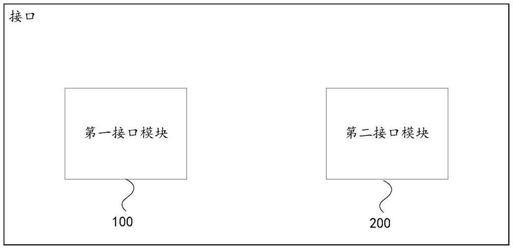
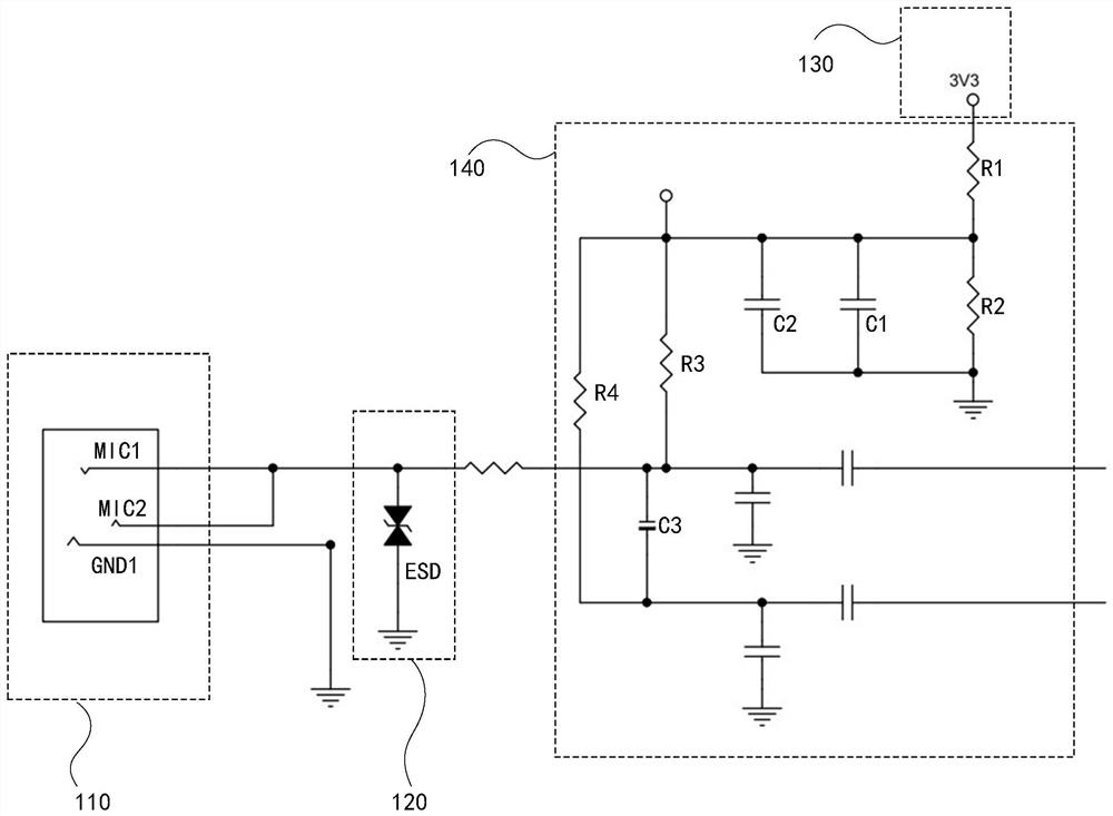
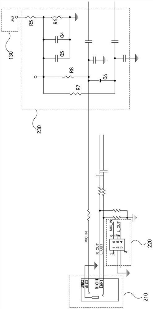
The invention discloses an earphone interface circuit and a terminal. The earphone interface circuit comprises a first interface module used for being electrically connected with a microphone plug of the earphone; and a second interface module, used for being electrically connected with an audio output plug of the earphone or an integrated plug of the earphone. According to the embodiment of the invention, the interface requirement of a double-3pin earphone can be met, and the interface requirement of a single-4pin earphone can also be met, so that the applicability of a product is improved, and the use cost of a user is reduced.

Description

technical field [0001] The invention relates to the technical field of earphone interface, in particular to an earphone interface circuit and a terminal. Background technique [0002] At present, there are two types of 3.5mm earphones, one is a single 4pin earphone, and the other is a double 3pin earphone. Wherein, the single 4pin earphone is an earphone including an integrated plug, and the integrated plug has both a microphone function and an audio output function. The double 3pin earphone is an earphone including two plugs, one plug is used for microphone signal input, and the other plug is used for audio signal output. [0003] In the related art, the interface of most products is a single 4pin plug interface. If the user needs to access the earphone with double 3pin plugs, he needs to use a two-in-one converter to convert the interface. This method not only increases the user's use cost, but also affect the suitability of the product. Contents of the invention [0...

Claims


Application Information

Patent Timeline
IPC IPC(8): H04R3/00H04R1/10
CPCH04R3/00H04R1/1091H04R2203/00H04R2201/10
Inventor 韦洁钊余毅鹏陈家劭吴树雄姚志兴张杰洪杨金河朱贝
Owner 深圳市天视通视觉有限公司
Why Eureka
Try Eureka