Steel structure box beam convenient to install and assembling method
An easy-to-install, box-shaped girder technology, applied to long-strip structural members, structural elements, truss-type structures, etc. for load-bearing, can solve the problems of time-consuming and labor-intensive installation, inconvenient installation, etc., and achieve easy separation and convenience Pull adjustment, fast and convenient assembly
- Summary
- Abstract
- Description
- Claims
- Application Information
AI Technical Summary
Problems solved by technology
Method used
Image
Examples
Embodiment 1
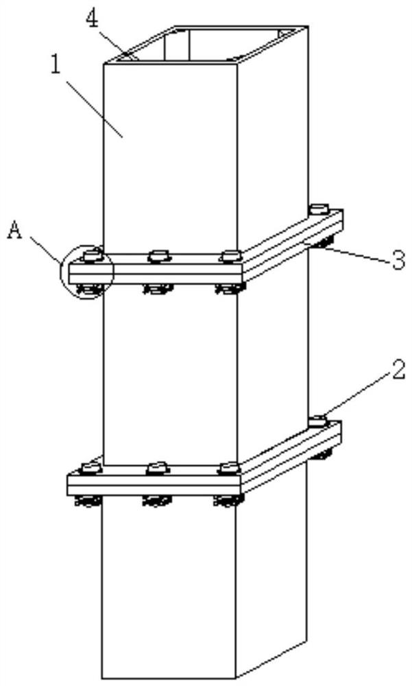
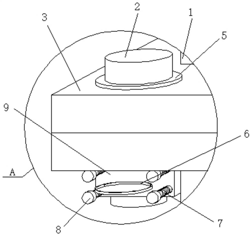
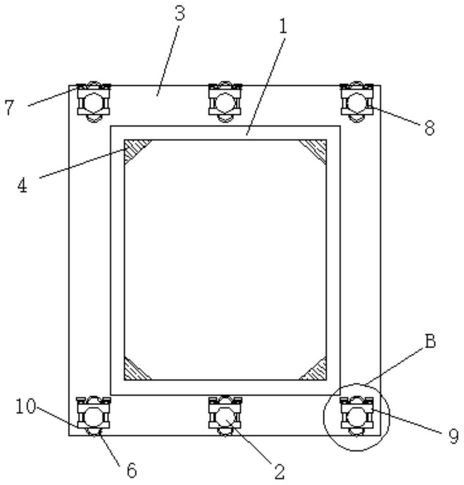
[0030] see Figure 1 to Figure 5 , the present invention provides a technical solution: a steel structure box girder for easy installation, including a box girder main body 1, an assembly frame 3 is sleeved on the end of the box girder main body 1, and the end face of the adjacent assembly frame 3 Fitting each other, the end surface of the assembly frame 3 is provided with an assembly hole, and the assembly column 2 runs through the inside of the assembly hole. Through the designed assembly column 2, assembly groove 12, assembly block 9 and connection block 10, the assembly column 2 passes through the After the assembly hole of the frame 3 is assembled, the assembly block 9 and the connecting block 10 are snapped into the assembly groove 12 at the other end of the assembly column 2 to realize fixing, which makes the assembly of the present invention quicker and more convenient, and the outer wall of one end of the assembly column 2 An assembly groove 12 is provided, and the tw...
Embodiment 2
[0034] see Figure 1 to Figure 5 , the present invention provides a technical solution: a steel structure box girder for easy installation, including a box girder main body 1, an assembly frame 3 is sleeved on the end of the box girder main body 1, and the end face of the adjacent assembly frame 3 Fitting each other, the end surface of the assembly frame 3 is provided with an assembly hole, and the assembly column 2 runs through the inside of the assembly hole. Through the designed assembly column 2, assembly groove 12, assembly block 9 and connection block 10, the assembly column 2 passes through the After the assembly hole of the frame 3 is assembled, the assembly block 9 and the connecting block 10 are snapped into the assembly groove 12 at the other end of the assembly column 2 to realize fixing, which makes the assembly of the present invention quicker and more convenient, and the outer wall of one end of the assembly column 2 An assembly groove 12 is provided, and the tw...
PUM
 Abstract
Description
Claims
Application Information
 - R&D
- Intellectual Property
- Life Sciences
- Materials
- Tech Scout
- Unparalleled Data Quality
- Higher Quality Content
- 60% Fewer Hallucinations
Browse by: Latest US Patents, China's latest patents, Technical Efficacy Thesaurus, Application Domain, Technology Topic, Popular Technical Reports.
© 2025 PatSnap. All rights reserved.Legal|Privacy policy|Modern Slavery Act Transparency Statement|Sitemap|About US| Contact US: help@patsnap.com


