Spine non-fusion internal fixator

An internal fixator and non-fusion technology, applied in the field of medical devices, can solve problems such as slippage and dislocation of the fixed rod, poor fixing effect of the fixed rod, etc., and achieve the effects of less displacement, avoiding secondary injury, and stable fixed position

Pending Publication Date: 2022-02-01
HEBEI PROVINCE CANGZHOU HOSPITAL OF INTEGRATED TRADITIONAL & WESTERN MEDICINE
View PDF0 Cites 0 Cited by
  • Summary
  • Abstract
  • Description
  • Claims
  • Application Information

AI Technical Summary

Problems solved by technology

[0003] When the existing spinal non-fusion internal fixator is in use, the operator fixes the root nail on the corresponding spine, and then passes the root nails fixed on the spine through the fixing rod for fixation, thereby achieving internal fixation. As a result, in the connection between the fixed rod and the end frame of the root nail, the compression nut is used for compression, which leads to poor fixing effect on the fixed rod, making it prone to the problem of slipping and dislocation of the fixed rod

Method used


Image

  • Spine non-fusion internal fixator
  • Spine non-fusion internal fixator
  • Spine non-fusion internal fixator

Examples


Embodiment 1

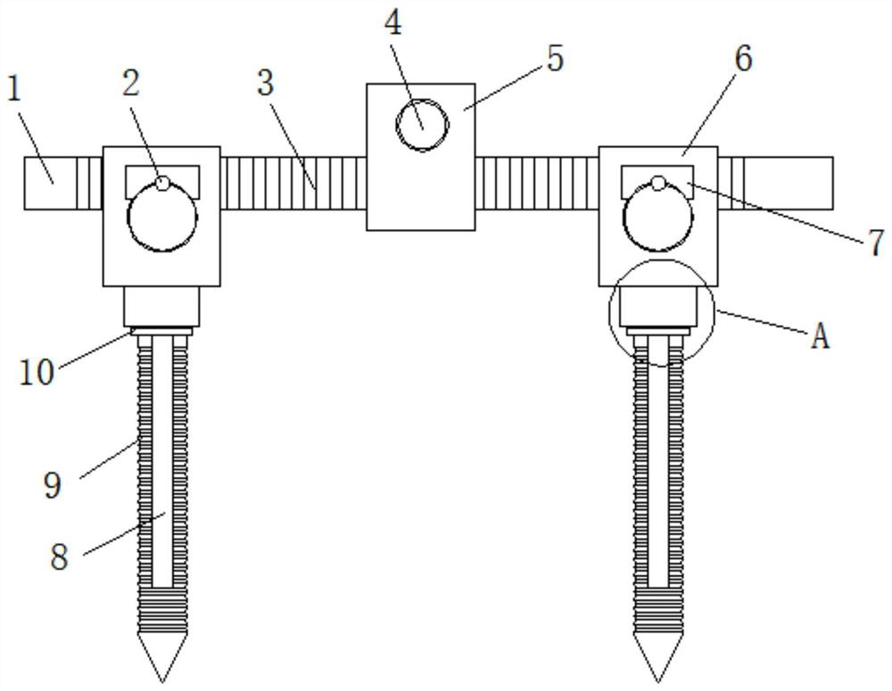
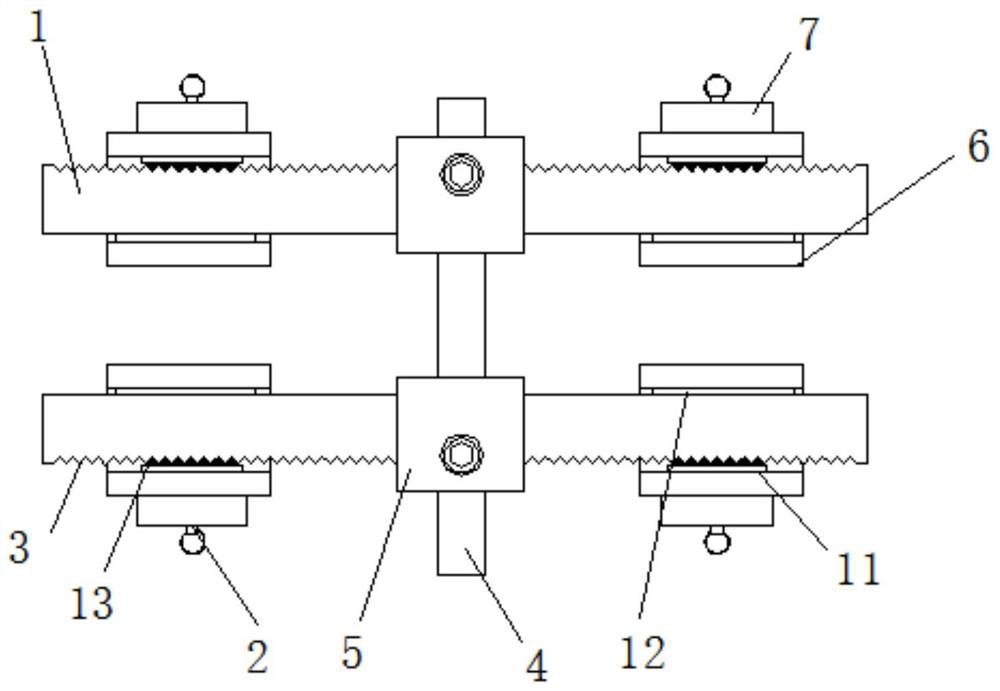
[0022] See Figure 1 to 3 The present invention provides a technical solution: a spine non-fusion internal fixator, including connecting rod 4, both ends of the connecting rod 4, have a sliding sleeve 5, and the inside of the slider 5 runs through the fixed bar 1, a fixed bar 1 The outer wall sleeve is provided with a terminal frame 6, and one end side of the end frame 6 is inlaid having a side frame 7, and the inside of the side frame 7 is provided with an end plate 11, and one end of the end plate 11 is fixed with a tooth block 13. The end plate 11, the side frame 7, and the tooth groove 3, the side frame 7 is mounted on the tip frame 6, and the end plate 11 containing the tooth 13 is located inside the side frame 7, thereby passing the fixed bar 1 and the end frame 6 through The jocket 13 card implements the engagement fixation in the tooth groove 3, ensuring that its fixed limit is more secure, is not easy to displace, and the outer wall of the fixing lever 1 is in a linear arr...

Embodiment 2

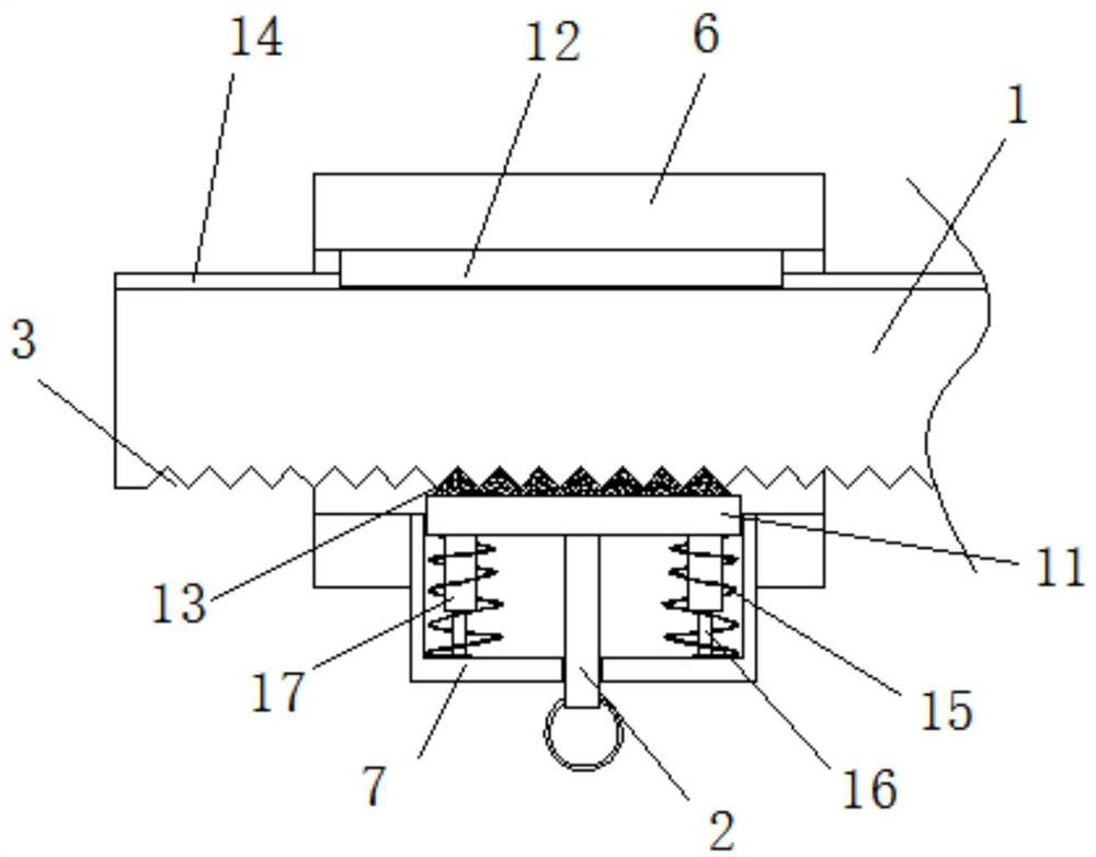
[0025] See Figure 1 to 4 The present invention provides a technical solution: a spine non-fusion internal fixator, including connecting rod 4, both ends of the connecting rod 4, have a sliding sleeve 5, and the inside of the slider 5 runs through the fixed bar 1, a fixed bar 1 The outer wall sleeve is provided with a terminal frame 6, and one end side of the end frame 6 is inlaid having a side frame 7, and the inside of the side frame 7 is provided with an end plate 11, and one end of the end plate 11 is fixed with a tooth block 13. The end plate 11, the side frame 7, and the tooth groove 3, the side frame 7 is mounted on the tip frame 6, and the end plate 11 containing the tooth 13 is located inside the side frame 7, thereby passing the fixed bar 1 and the end frame 6 through The jocket 13 card implements the engagement fixation in the tooth groove 3, ensuring that its fixed limit is more secure, is not easy to displace, and the outer wall of the fixing lever 1 is in a linear arr...


PUM


Abstract

The invention discloses a spine non-fusion internal fixator which comprises a connecting rod, the two ends of the connecting rod are sleeved with sliding sleeves, a fixing rod penetrates through the sliding sleeves, the outer wall of the fixing rod is sleeved with an end frame, a side frame is embedded in the side portion of one end of the end frame, and an end plate is arranged in the side frame. A tooth block is fixed to one end of the end plate, tooth grooves are formed in one side of the outer wall of the fixing rod in a linear array mode, one end of the tooth block is arranged in the tooth grooves, and a pull rod is fixed to the center of the surface of the other end of the end plate. The end plate, the side frame and the tooth grooves are designed, the side frame is installed on the end frame, and the end plate provided with the tooth block is located in the side frame, so that the fixing rod and the end frame are clamped and fixed in the tooth grooves through the tooth block, it is guaranteed that the fixing and limiting are more stable, displacement is not likely to happen, and the tooth block can be pulled and adjusted conveniently through the designed pull rod.

Description

Technical field [0001] The present invention belongs to the technical field of medical devices, and in particular to a spine non-fusion internal fixator. Background technique [0002] Surgery for treating spinal bending, especially the spine of adolescents and children, when the internal fixation, the internal fixation of the internal fixation, to maintain the effect of the surgery, increase the spinal bone fusion rate, the spine non-fusion internal fixator is A non-fusion fixing assembly for spinal deformation treatment, connecting its spine through a holder to correct restrictions, making it recovering. [0003] When the existing spine is in use, the operator fixes its root nail on the corresponding spine, and then fixes the root nu fixed on the spine together by the fixed bar to reach the internal fixation. Effect, in the connection of the terminal frame of the fixing rod and the root nail, use the pressure-solid nut to cause pressure, resulting in poor fixation effect on the ...

Claims


Application Information

Patent Timeline
IPC IPC(8): A61B17/70
CPCA61B17/7002A61B17/7043A61B17/705
Inventor 郭巍穆坤石家晓赵保辉陶晓冰李浩然
Owner HEBEI PROVINCE CANGZHOU HOSPITAL OF INTEGRATED TRADITIONAL & WESTERN MEDICINE
Why Eureka
Try Eureka