End grinding device for screw rod machining

A technology of screw and lifting rod, which is applied in the field of end grinding devices for screw processing, can solve problems such as inconvenient fixing, and achieve the effects of saving time and improving work efficiency

Active Publication Date: 2017-10-03
天津泰鼎晟业传动技术发展有限公司
View PDF5 Cites 3 Cited by
  • Summary
  • Abstract
  • Description
  • Claims
  • Application Information

AI Technical Summary

Problems solved by technology

[0004] Aiming at the deficiencies of the prior art, the present invention provides an end gr...

Method used


Image

  • End grinding device for screw rod machining
  • End grinding device for screw rod machining
  • End grinding device for screw rod machining

Examples


Embodiment Construction

[0018] The following will clearly and completely describe the technical solutions in the embodiments of the present invention with reference to the accompanying drawings in the embodiments of the present invention. Obviously, the described embodiments are only some, not all, embodiments of the present invention. Based on the embodiments of the present invention, all other embodiments obtained by persons of ordinary skill in the art without making creative efforts belong to the protection scope of the present invention.

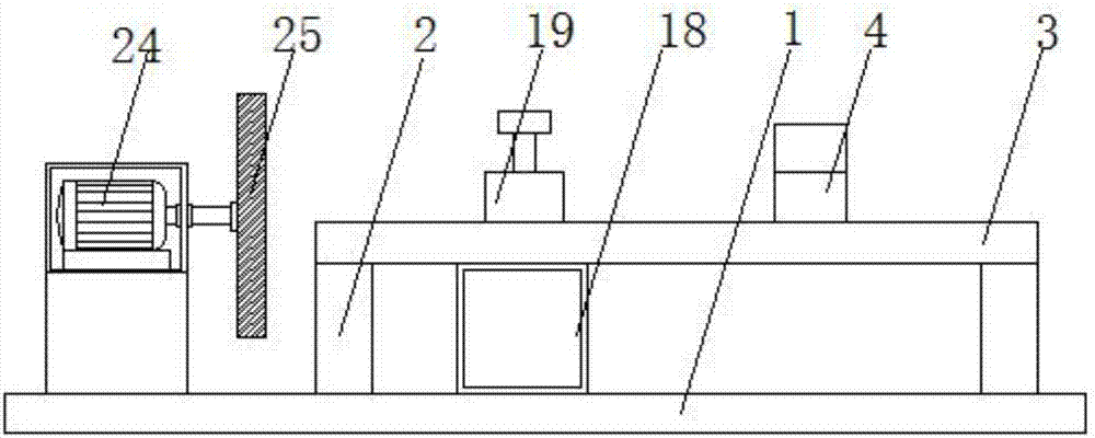
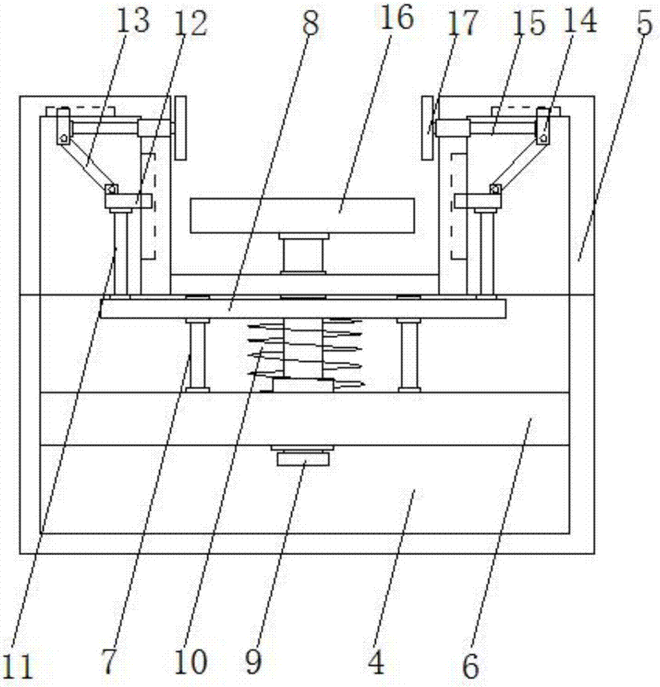
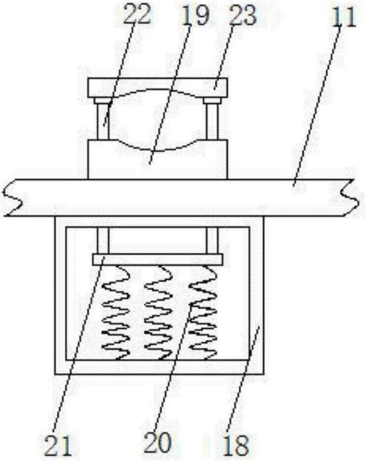
[0019] see Figure 1-3 , the present invention provides a technical solution: an end grinding device for lead screw processing, including a base 1, the top of the base 1 is fixedly installed with a horizontal plate 3 through the legs 2, and a lifting box is fixedly installed on the top of the horizontal plate 3 4. Risers 5 are fixedly installed on both sides of the lifting box 4, a partition 6 is fixedly installed in the inner cavity of the lifting box 4, and ...


PUM


Abstract

The invention discloses an end grinding device for screw rod machining, and relates to the technical field of screw rod machining. The end grinding device for screw rod machining comprises a base, a horizontal plate is fixedly mounted at the top end of the base through supporting legs, a lifting box is fixedly mounted at the top end of the horizontal plate, and vertical boxes are fixedly mounted on the upper portions of the two sides of the lifting box; a separating plate is fixedly mounted in an inner cavity of the lifting box, a sliding rod is fixedly mounted between the top end of the separating plate and a top plate o the lifting box, and the surface of the sliding rod is slidably connected with a lifting plate; and a first lifting rod is fixedly arranged in the lifting plate, the top end of the first lifting rod penetrates through the top plate of the lifting box and extends above the lifting box, and a first spring is fixedly mounted between the bottom end of the lifting plate and the top end of the separating plate and located on the lifting rod. The side face of a screw rod is clamped by clamping plates through a first cushion plate, the first lifting rod, the lifting plate, clamping rods and other elements, and thus the screw rod can be quickly fixed, time is saved, and work efficiency is improved.

Description

technical field [0001] The invention relates to the technical field of lead screw processing, in particular to an end grinding device for lead screw processing. Background technique [0002] Ball screw is an ideal product for converting rotary motion into linear motion, or converting linear motion into rotary motion; ball screw is the most commonly used transmission element in tool machinery and precision machinery, and its main function is to convert rotary motion into linear motion, or convert torque into axial repetitive force, while combining the characteristics of high precision, reversibility and high efficiency. Due to its small frictional resistance, ball screws are widely used in various industrial equipment and precision instruments; ball screw bearings provide a wide variety of standardized products to suit various purposes. Widely used in machine tools, the circulation methods of balls include circulation conduit type, circulator type, and end cover type. Prelo...

Claims


Application Information

Patent Timeline
IPC IPC(8): B24B7/16B24B41/06
CPCB24B7/16B24B41/06
Inventor 叶雷
Owner 天津泰鼎晟业传动技术发展有限公司
Why Eureka
Try Eureka