Cast-in-situ cantilever construction hanging basket system

A technology of I-type and bottom plate, which is applied in the direction of erecting/assembling bridges, bridges, buildings, etc., can solve the problems of long construction period, complicated process, and difficult casing positioning, and achieve strong deformation resistance and easy socketing and fixing Effect

Pending Publication Date: 2019-12-03
曾勇
View PDF7 Cites 2 Cited by
  • Summary
  • Abstract
  • Description
  • Claims
  • Application Information

AI Technical Summary

Problems solved by technology

The disadvantage is that the deformation of the hanging basket and the influence of concrete shrinkage and creep must be strictly controlled during the entire construction process. Compared with other construction methods, the construction period is longer, and the process of pouring a section of concrete must be adjusted in stages. cable, the process is complicated, and the casing positioning between the hanging basket and the stay cable is difficult

Method used


Image

  • Cast-in-situ cantilever construction hanging basket system
  • Cast-in-situ cantilever construction hanging basket system
  • Cast-in-situ cantilever construction hanging basket system

Examples


Embodiment 1

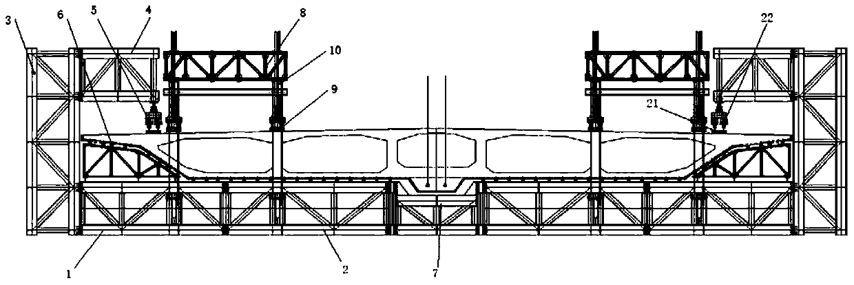
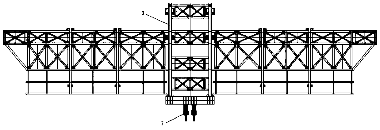
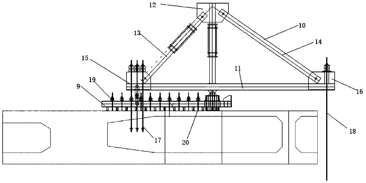
[0055] figure 1 It is the front view of the suspended construction hanging basket system of an embodiment of the present invention. figure 2 It is a side view of the suspended construction hanging basket system according to an embodiment of the present invention. image 3 It is a schematic structural diagram of an auxiliary hanger according to an embodiment of the present invention. Figure 4 It is a schematic structural diagram of an under-beam traction device according to an embodiment of the present invention.

[0056] Such as Figure 1-4 As shown, taking the construction of a certain bridge as an example, the main bridge of the bridge adopts a (100m+100m) single-tower single-cable-plane cable-stayed bridge. , 40m prefabricated partially prestressed concrete composite box girder. The starting point of the bridge is K0+262.833, across Binhe Avenue, Luohe North Embankment, Luo River, Luohe River, and the end point is K1+113.333. The span layout of the whole bridge is (4...


PUM


Abstract

The embodiment of the invention discloses a cast-in-situ cantilever construction hanging basket system of a cable-stayed bridge. The cast-in-situ cantilever construction hanging basket system of the cable-stayed bridge comprises a hanging basket main body, a hanging basket form and under-beam traction devices. The hanging basket main body comprises a bottom plate, hook stand columns, hooks and a walking mechanism, wherein the bottom plate is used for being arranged at the bottom of a main beam; one ends of the hook stand columns are connected to the bottom plate, and the hook stand columns arearranged at the two ends of the bottom plate; the hooks are connected to the other ends of the hook stand columns; and the walking mechanism is connected to the hooks. The hanging basket form is arranged at the top of the bottom plate and located between the main beam and the bottom plate. The under-beam traction devices are arranged on the two sides of the bottom of the bottom plate, wherein theunder-beam traction devices can penetrate through the bottom plate so as to be connected with a stay cable of the cable-stayed bridge. The cast-in-situ cantilever construction hanging basket system has the advantages of being stronger in anti-deformation capability and making sleeving of the stay cable more convenient.

Description

technical field [0001] The invention relates to the field of bridge construction, in particular to a hanging basket system for cantilever construction. Background technique [0002] The cantilever casting method is mainly used on cable-stayed bridges with prestressed concrete girders. The cantilever pouring of the main girder concrete is basically the same as that of the general prestressed concrete girder bridge. Use the stay cables of the beam section to be poured as the front fulcrum of the hanging basket, and anchor the rear end of the hanging basket on the poured beam section during the construction process. The weight of the concrete beam section of the section to be poured is jointly undertaken by the stay cables and the poured beam section. After the concrete of the main beam reaches the design strength, remove the connection between the stay cables and the hanging basket, so that the segmental gravity is transferred to the stay cables, and then move the hanging ba...

Claims


Application Information

Patent Timeline
IPC IPC(8): E01D21/10
CPCE01D21/10
Inventor 曾勇马长江张浩黄山峰姬梦龙赵鹊梁西建张涛曾利
Owner 曾勇
Why Eureka
Try Eureka