Composite beam and composite beam and column joint connecting device

A technology of connecting device and composite beam, applied in the direction of joists, girders, truss beams, etc., can solve the problems of unbalanced force at the joint, weak connection of beams and columns, and easy damage of connecting screws, etc., to achieve balanced force, Good anti-corrosion performance and the effect of reducing load-bearing pressure

Active Publication Date: 2019-10-18
NORTH CHINA UNIV OF WATER RESOURCES & ELECTRIC POWER
View PDF10 Cites 0 Cited by
  • Summary
  • Abstract
  • Description
  • Claims
  • Application Information

AI Technical Summary

Problems solved by technology

[0004] Aiming at the deficiencies of the prior art, the present invention provides a composite beam and composite beam and column joint connection device, the purpose is to solve the problem that the existing steel beam is exposed to the external environment and has poor corrosion resistance; the existing beam and column joint connection, the connection Unbalanced force, easy damage to connecting screws, bending deformation and cracking of connecting plates, and weak connection between beams and columns

Method used


Image

  • Composite beam and composite beam and column joint connecting device
  • Composite beam and composite beam and column joint connecting device
  • Composite beam and composite beam and column joint connecting device

Examples


Embodiment Construction

[0027] The present invention will be further described below in conjunction with the accompanying drawings and specific embodiments.

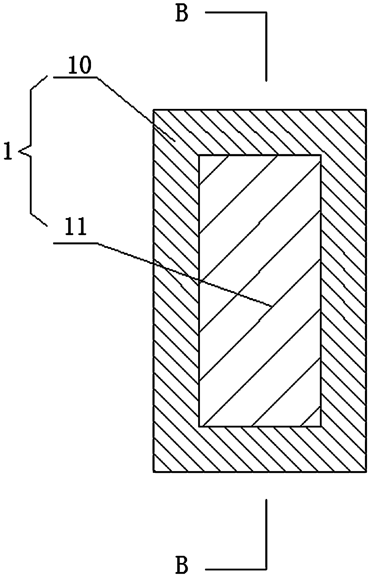
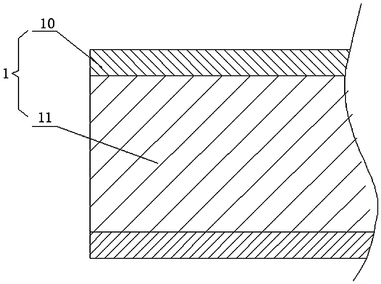
[0028] Such as Figure 1 to Figure 9 As shown, a composite beam 1, a shell 10 and a core 11, the shell 10 is a column with a "back" shape in section, the material of the shell 10 is aluminum, and the core 11 is worn on the shell For the rectangular cylinder in 10, the material of the core 11 is different from that of the shell 10, the Young's modulus of the core 11 is greater than that of the shell 10, and the core 11 is made of steel.

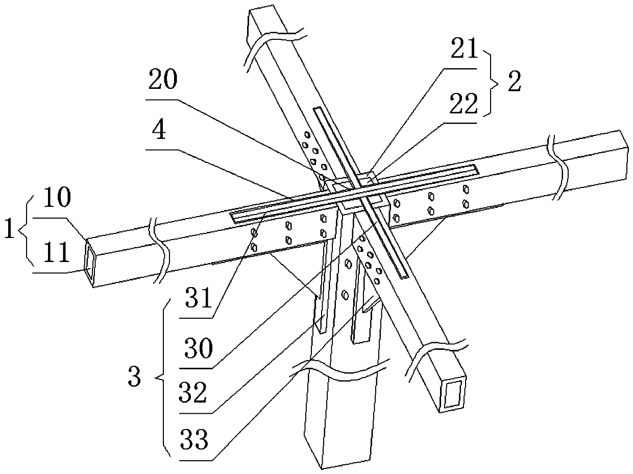
[0029] A composite beam and column joint connection device, comprising a composite beam 1, a support column 2 and a connecting bracket 3, the support column 2 is a vertical rectangular column, and the upper parts of the four sides of the support column 2 are respectively provided with Horizontal composite beam 1, the upper end of the support column 2 is provided with a "ten"-shaped opening 20, the end surface ...


PUM


Abstract

The invention relates to a composite beam. The composite beam comprises a shell and a core. The shell is a column with a double-homocentric-square-shaped section. The shell is made from aluminum, andthe material of the core is different from the material of the shell. A composite beam and column joint connecting device comprises the composite beams, a supporting column and a connecting support, and the horizontal composite beams are arranged on the upper portions of the four side faces of the supporting column correspondingly. A cross-shaped opening is formed in the upper end of the supporting column, and rectangular grooves are formed in the end faces, attached to the supporting column, of the composite beams. The rectangular grooves communicate with the tail ends of the cross-shaped opening correspondingly. The connecting support is inserted into the cross-shaped opening of the supporting column and the rectangular grooves of the composite beams. The support and the supporting column are connected through screws, and the connecting support and the composite beams are connected through screws. The composite beam and the composite beam and column joint connecting device aim at solving the problems the an existing steel beam is exposed to the external environment and is poor in corrosion resistance, existing beams and columns are in joint connection, the joint is unbalanced instress, connecting screws are likely to be damaged, a connecting plate is likely to be bent, deform and crack, and connection of the beams and the columns are not firm.

Description

technical field [0001] The invention relates to the field of building construction, in particular to a composite beam and a joint connection device between a composite beam and a column. Background technique [0002] Beams support the entire weight of the components in the upper frame of the building and the roof, and are the most important part of the upper frame of the building. Beams must have good bending resistance, firmness, and corrosion resistance. [0003] Existing beams generally adopt steel structures, which are exposed to the external environment and have poor corrosion resistance; the existing beams and columns are connected by joints, and the connecting plates are fixed on the outside of the beams and columns by screws. Due to high stress concentration, the screws are easily damaged, the connecting plates are prone to bending deformation and cracking, and the connection of beams and columns is not firm. Contents of the invention [0004] Aiming at the defici...

Claims


Application Information

Patent Timeline
IPC IPC(8): E04B1/24E04B1/58E04C3/06
CPCE04B1/24E04B1/2403E04B2001/2415E04B2001/2418E04B2001/2466E04C3/06
Inventor 郝颖
Owner NORTH CHINA UNIV OF WATER RESOURCES & ELECTRIC POWER
Why Eureka
Try Eureka