
Automatic constant-speed push rod propelling device

A technology of propulsion device and push rod, which is applied in tunnel engineering and mining fields to achieve the effect of reducing manual workload, increasing stability and improving test results

Pending Publication Date: 2021-09-17
CHINA UNIV OF MINING & TECH (BEIJING)
View PDF0 Cites 2 Cited by
  • Summary
  • Abstract
  • Description
  • Claims
  • Application Information

AI Technical Summary

Problems solved by technology

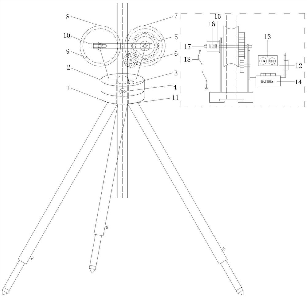
[0003] The object of the present invention is to provide an automatic push rod propulsion device at a constant speed to solve the above-mentioned problems of manual operation, so that by relying on this device, the push rod can be fixed, and the push rod can be automatically and uniformly sent into the drill hole, and then come Reduce the manual workload of testing, simplify the testing process, and improve the effectiveness and efficiency of testing

Method used


Image

  • Automatic constant-speed push rod propelling device
  • Automatic constant-speed push rod propelling device
  • Automatic constant-speed push rod propelling device

Examples


Embodiment Construction

[0021] The following will clearly and completely describe the technical solutions in the embodiments of the present invention with reference to the accompanying drawings in the embodiments of the present invention. Obviously, the described embodiments are only some, not all, embodiments of the present invention. Based on the embodiments of the present invention, all other embodiments obtained by persons of ordinary skill in the art without making creative efforts belong to the protection scope of the present invention.

[0022] The object of the present invention is to provide an automatic push rod propulsion device at a constant speed to solve the above-mentioned problems of manual operation, so that by relying on this device, the push rod can be fixed, and the push rod can be automatically and uniformly sent into the drill hole, and then Reduce the manual workload of the test, simplify the test process, and improve the test effect and effect.

[0023] In order to make the ab...


PUM


Abstract

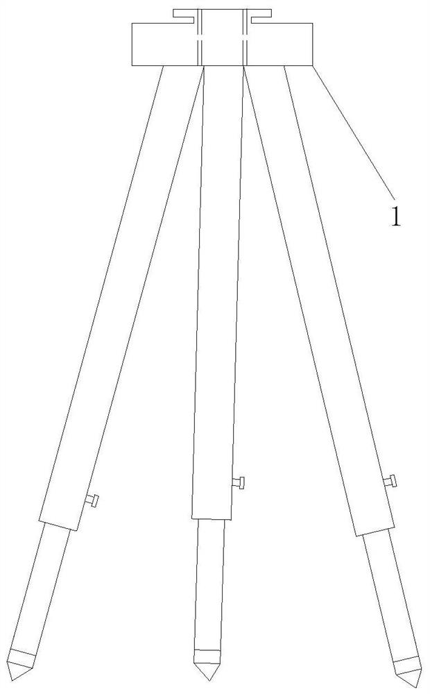
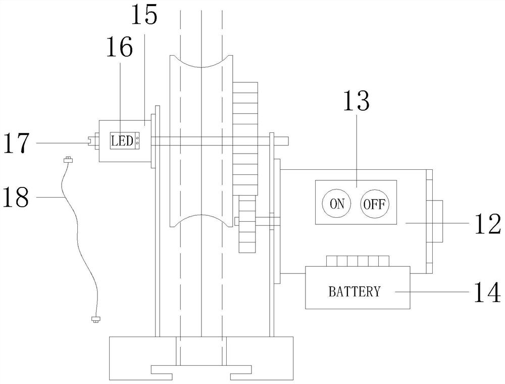
The invention discloses an automatic constant-speed push rod propelling device. The automatic constant-speed push rod propelling device comprises a tripod base device, a base device, a bubble leveling device, a motor gear transmission device, a roller clamping and propelling device, a depth encoder, an LED display device and the like, wherein the bubble leveling device, the motor gear transmission device, the roller clamping and propelling device, the depth encoder and the LED display device are fixed on the base, the base device is clamped with the tripod base device. During working, a push rod is inserted between two roller grooves and is tensioned by the tensioning device; a detachable rechargeable battery supplies power, a motor runs at a constant speed to drive the push rod to rise at a constant speed, the motor has overload protection, and if the push rod is clamped, power can be automatically cut off, and rod feeding is stopped; the depth encoder rotates through a roller and outputs a pulse signal, on one hand, the pushing depth of the push rod is directly displayed through a LED display screen, and on the other hand, the depth encoder can be connected to a peeping instrument host through a data cable to cooperatively complete video acquisition, image splicing and other work; and a switch button ensures that equipment is stopped and started at any time, and drill rod connection is facilitated. The equipment has the functions of clamping and fixing the push rod, automatically pushing the push rod at a constant speed, displaying the pushing depth, outputting a depth signal and the like, and can be well matched with and assist other equipment to finish drilling, peeping and the like.

Description

technical field [0001] The invention relates to the fields of mine and tunnel engineering, in particular to an automatic constant-speed push rod propelling device used in cooperation with engineering surveys such as borehole peeping and trajectory imaging. Background technique [0002] Borehole peeping and trajectory imaging technologies are currently widely used in engineering fields such as mines and tunnels in my country. In the process of testing, ensuring the stability and uniform speed of the push rod is the key to the success of the test and the test effect. In order to achieve a higher measurement depth, it is necessary to continuously connect the push rod; in order to ensure the effect of testing and imaging, it is necessary to send the push rod into the borehole at a constant speed. At present, this work is mainly done manually, with one person holding the push rod, and ensuring that the push rod is sent into the borehole at a uniform speed as possible, and one pe...

Claims


Application Information

Patent Timeline
Patent Type & Authority Applications(China)
IPC IPC(8): E21B23/00E21B47/002E21B47/04F16M11/32
CPCE21B23/00E21B47/04F16M11/32
Inventor 杨胜利刘传义刘垚
Owner CHINA UNIV OF MINING & TECH (BEIJING)
Learn More