A device for detecting yarn quality and controlling waste yarn diversion in the production process

A technology for yarn quality and production process, which is applied in the field of yarn quality detection and control of waste thread diversion equipment, to ensure the diversion effect, help popularize use, and reduce labor intensity.

Active Publication Date: 2022-02-25
NANTONG JINSHAN TEXTILE
View PDF14 Cites 0 Cited by
  • Summary
  • Abstract
  • Description
  • Claims
  • Application Information

AI Technical Summary

Problems solved by technology

[0004] The object of the present invention is to provide a kind of equipment that detects the yarn quality and controls the diversion of waste yarn in the production process, so as to solve the relevant problems raised in the above-mentioned background technology

Method used


Image

  • A device for detecting yarn quality and controlling waste yarn diversion in the production process
  • A device for detecting yarn quality and controlling waste yarn diversion in the production process
  • A device for detecting yarn quality and controlling waste yarn diversion in the production process

Examples


Embodiment 1

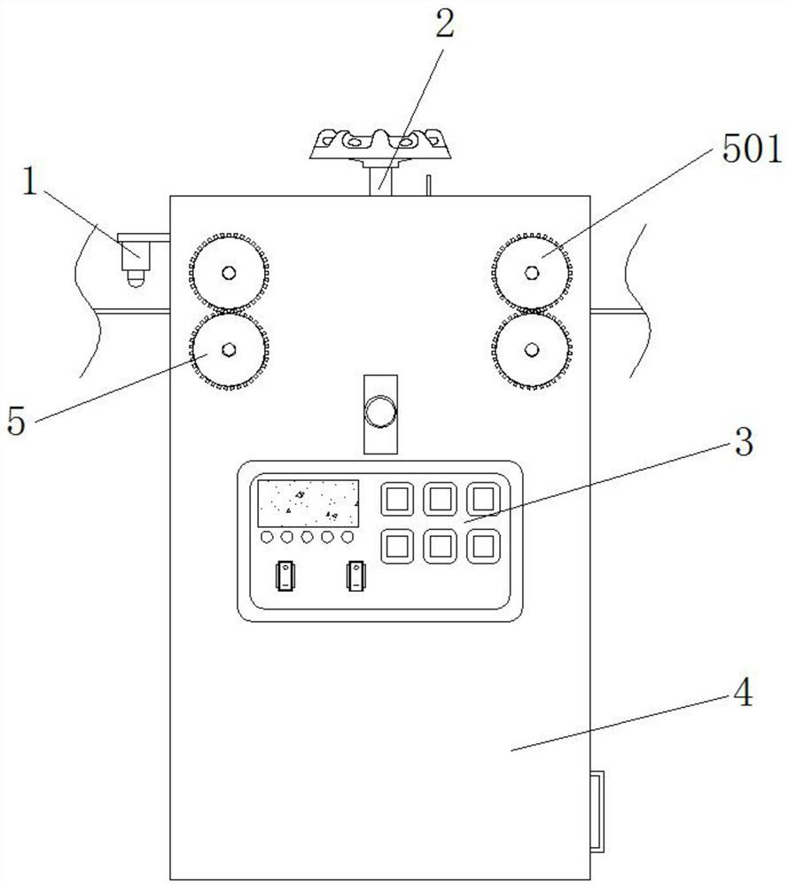
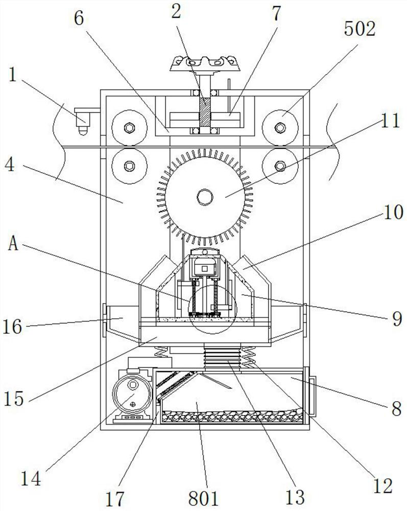
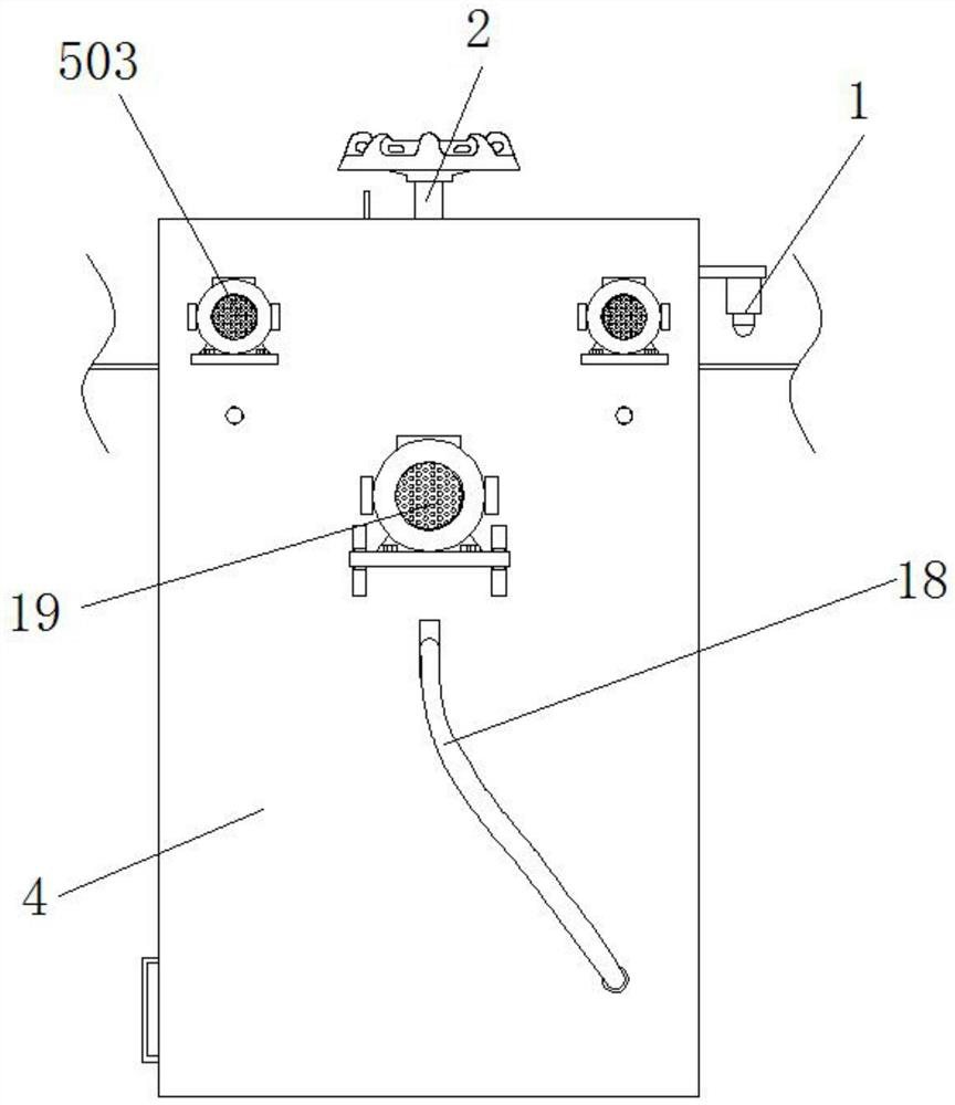
[0039] Example 1, such as Figure 1-7 As shown, when the yarn moves between the two pairs of guide rollers 502, the first threaded rod 2 is manually rotated first, and the U-shaped movable frame 7 is controlled to rise or fall by the thread action, thereby adjusting the distance between the bristles 25 and the yarn , then directly control the driving device 19 to drive the rotating cylinder 11 to rotate, use the rotating bristles 25 to brush off the waste thread on the yarn, and at the same time control the work of the air pump 14, so that the air in the main body compartment 4 passes through the first recovery compartment respectively 10 and the second recovery bin 16 enter the inside of the collection bin 15, and then enter the inside of the collection bin 801 through the telescopic tube 13, and part of the waste lines flying inside the main body bin 4 will be sucked in by the second recovery bin 16, thereby completing the collection. Yarn shunt treatment to avoid waste thre...

Embodiment 2

[0040] Example 2, such as Figure 1-8 As shown, when some waste threads are hung between the bristles 25, the second servo motor 901 can be controlled by the control panel 3 to drive the rotating rod 905 to rotate, and the transmission of the driven gear 904 and the driving gear 908 can be used to drive two groups of second threads. Rod 906 rotates, and due to thread effect, one group of lifting plates 903 rises, and another group of lifting plates 903 descends, and the movable rod 907 on the rising lifting plate 903 can move between multiple groups of bristles 25, and the bristles between bristles 25 The waste thread is scraped to clean the waste thread on the bristles 25, and when the movable rod 907 with the waste thread is retracted into the interior of the installation chamber 902, the waste thread will not enter the interior of the installation chamber 902, but fall off On both sides of the top of the installation bin 902, the waste thread that loses attachments is quick...


PUM


Abstract

The invention discloses a device for detecting yarn quality and controlling the shunting of waste threads in the production process. A first threaded rod is provided at the middle position, and a U-shaped movable frame is arranged on the outer thread of the first threaded rod, and a rotating cylinder is arranged at the middle position of both ends of the U-shaped movable frame, and the outer side of the rotating cylinder is uniform Set with bristles. In the present invention, through the cooperative use of the U-shaped movable frame, the cleaning assembly, the first recovery bin, the collection bin and the second recovery bin, after controlling a group of lifting plates to rise, the bristles are moved between the bristles by multiple groups of movable rods on the group of lifting plates. scrape the waste thread to reduce the amount of waste thread attached between the bristles, and after the movable rod is retracted into the interior of the installation compartment, the waste thread hung on the movable rod will be quickly sucked into the interior of the first recovery compartment, so that the The structure can continuously clean the waste thread attached to the bristles.

Description

technical field [0001] The invention relates to the technical field of yarn production and processing equipment, in particular to equipment for detecting yarn quality and controlling waste yarn diversion during production. Background technique [0002] The loom will produce some waste threads such as broken threads during the production process. The existence of waste threads will affect the quality of the finished fabric and affect the normal operation of the loom. At this time, it is necessary to remove the waste threads to avoid more waste threads. The thread remains on the fabric, affecting the quality of the fabric. [0003] At present, when the waste thread in the yarn is separated, the waste thread is usually sorted out and taken out manually, which is very time-consuming, inefficient, and the labor intensity of the cleaning personnel is high, and the waste thread cannot be separated efficiently for a long time ; and when the current equipment shunts the waste thread...

Claims


Application Information

Patent Timeline
Patent Type & Authority Patents(China)
IPC IPC(8): G01N21/84G01N21/01B08B1/00B08B7/02B01D46/76B01D46/12
CPCG01N21/84G01N21/01B08B1/00B08B7/02B01D46/12
Inventor 洪金山马修芳
Owner NANTONG JINSHAN TEXTILE
Why Eureka
Try Eureka