Constant-power aging circuit for output end of photoelectric coupler

A photoelectric coupler and burn-in circuit technology, which is applied in the direction of instruments, measuring electricity, and adjusting electrical variables, etc., can solve the problems of unstable aging power of triodes, uncontrolled quality and reliability, and poor aging reliability, etc., to achieve The effect of large tolerance, good batch consistency and simple circuit

Pending Publication Date: 2021-09-17
CHINA ZHENHUA GRP YONGGUANG ELECTRONICS CO LTD STATE OWNED NO 873 FACTORY
View PDF0 Cites 1 Cited by
  • Summary
  • Abstract
  • Description
  • Claims
  • Application Information

AI Technical Summary

Problems solved by technology

[0016] The present invention aims to solve the problems of unstable aging power of the triode at the output end of the photocoupler in the existing aging circuit, large fluctuations, poor aging reliability, uncontrolled quality and reliability, and high aging cost.

Method used


Image

  • Constant-power aging circuit for output end of photoelectric coupler
  • Constant-power aging circuit for output end of photoelectric coupler
  • Constant-power aging circuit for output end of photoelectric coupler

Examples


Embodiment 1

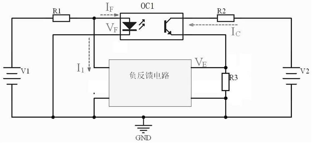
[0061] Embodiment 1: ( Figure 5 )

[0062] The negative feedback circuit is realized by the common emitter circuit composed of NPN transistor Q2. The input end of the negative feedback circuit is the BE pole, and the output end of the negative feedback circuit is the CE pole. The NPN transistor Q2 is 2N3904.

Embodiment 2

[0063] Embodiment 2: ( Figure 6 )

[0064] The negative feedback circuit is realized by a compound transistor composed of PNP transistor Q1 and NPN transistor Q2. The base of Q1 is connected to the collector of Q2, the collector of Q1 is connected to the emitter of Q2 and grounded, the input terminal of the negative feedback circuit is the BE pole of Q2, and the output terminal of the negative feedback circuit is the CE pole of Q1. The PNP transistor Q1 is 2N3906, and the NPN transistor Q2 is 2N3904.

Embodiment 3

[0065] Embodiment 3: ( Figure 7 )

[0066] The negative feedback circuit is realized by the operational amplifier A1. The input terminal of the negative feedback circuit is the input terminal of A1, and the output terminal of the negative feedback circuit is the output terminal of A1. The operational amplifier A1 is a high-precision operational amplifier with high input impedance.

[0067] Such as Figure 5 A constant power burn-in circuit at the output of an optocoupler is shown:

[0068] Analysis of the principle of steady current and voltage regulation:

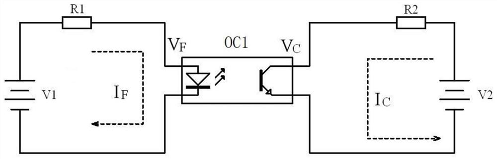
[0069] Taking Example 1 as an example, such as Figure 5 As shown, regardless of Q2 and R3, when V1 is powered on, a forward current I is provided to the light-emitting diode at the input end of the optocoupler. F , the light-emitting diode works, drives the phototransistor at the output end to conduct, and generates I C The relationship between current, IC and IF is determined by the CTR of the optocoupler:

[00...


PUM


Abstract

The invention discloses a constant-power aging circuit for an output end of a photoelectric coupler, and relates to the technical field of component aging. The constant-power aging circuit comprises a power supply V1, a power supply V2, an input end constant current module, an optocoupler to be aged, an output end current-limiting voltage difference-stabilizing module, an output end constant current control module and an output current sampling module. One end of the input end constant current module is connected with the positive electrode of the V1, the other end of the input end constant current module is connected with the input unit positive electrode end of the optocoupler to be aged and the positive output end of the output end constant current control module, and one end of the output end current-limiting voltage difference-stabilizing module is connected with the positive electrode of the V2, and the other end of the output end constant current module is connected with the positive electrode end of the output unit of the optocoupler to be aged. One end of the output current sampling module is connected with the negative electrode end of the output unit of the optocoupler to be aged, and the other end is grounded; the input end of the output end constant current control module is connected in parallel with the two ends of the output current sampling module, and the output end is connected in parallel with the two ends of the input unit of the optocoupler to be aged. The problems that an existing aging circuit is unstable in aging power, uncontrollable in quality, high in cost and the like are solved, and the circuit is widely applied to aging circuits of photoelectric couplers.

Description

technical field [0001] The invention relates to the technical field of aging of components, in particular to an aging circuit of a photoelectric coupler. Background technique [0002] Optocouplers (referred to as optocouplers) are used in occasions that require electrical physical isolation to transmit signals. The transmission process is: the input end converts electrical signals into optical signals, and the output end receives optical signals and converts them into electrical signals; its input end It is physically isolated from the output terminal, usually the input terminal is a light-emitting diode, and the output terminal is a phototransistor. [0003] At present, the burn-in screening for optocouplers is divided into two steps: input burn-in and output burn-in. When aging and screening the output terminal, it is necessary to apply a certain forward current I to the light-emitting diode inside the optocoupler F , and at the same time apply a specified power to the p...

Claims


Application Information

Patent Timeline
Patent Type & Authority Applications(China)
IPC IPC(8): G01R31/00G05F1/66G05F1/46
CPCG01R31/003G05F1/66G05F1/46
Inventor 代骞王智钱军军吕前进任真伟郭俊峰周卓方明洪简青青
Owner CHINA ZHENHUA GRP YONGGUANG ELECTRONICS CO LTD STATE OWNED NO 873 FACTORY
Why Eureka
Try Eureka