Optical lens and imaging equipment

A technology of optical lens and imaging surface, which is applied in the field of imaging lens, can solve the problems of poor imaging effect, small focal length, and inability to produce similar microscope effects, etc., and achieve clearer and more subtle picture features, small size, and optimized imaging effect.

Active Publication Date: 2021-11-02
JIANGXI LIANYI OPTICS CO LTD
View PDF3 Cites 0 Cited by
  • Summary
  • Abstract
  • Description
  • Claims
  • Application Information

AI Technical Summary

Problems solved by technology

In related technologies, the current macro lens has poor imaging effect and small focal length, which cannot produce a microscope-like effect

Method used


Image

  • Optical lens and imaging equipment
  • Optical lens and imaging equipment
  • Optical lens and imaging equipment

Examples


no. 1 example

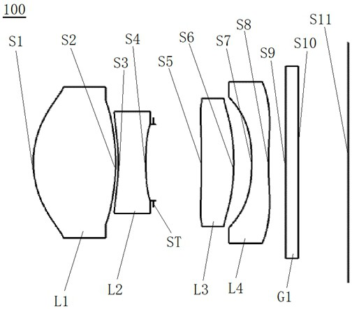
[0078] see figure 1 , which is a schematic structural view of the optical lens 100 provided by the first embodiment of the present invention, the optical lens 100 includes in sequence from the object side to the imaging surface along the optical axis: a first lens L1, a second lens L2, a diaphragm ST, a second lens Three lenses L3, a fourth lens L4 and a filter G1.

[0079] The first lens L1 has a positive refractive power, the object side S1 of the first lens is a convex surface, and the image side S2 of the first lens is a convex surface;

[0080] The second lens L2 has negative refractive power, the object side S3 of the second lens is concave, and the image side S4 of the second lens is concave;

[0081] The third lens L3 has positive refractive power, the object side S5 of the third lens is concave, and the image side S6 of the third lens is convex;

[0082] The fourth lens L4 has negative refractive power, the object side S7 of the fourth lens is concave, and the image...

no. 2 example

[0093] see Image 6 , which is a schematic structural view of the optical lens 200 provided in this embodiment, the structure of the optical lens 200 in this embodiment is roughly the same as that of the optical lens 100 in the first embodiment, the difference is that the optical lens in this embodiment The radius of curvature and thickness of each lens of the lens 200 are selected differently.

[0094] The relevant parameters of each lens in the optical lens 200 provided in this embodiment are shown in Table 3.

[0095] table 3

[0096]

[0097] The surface coefficients of each aspheric surface of the optical lens 200 in this embodiment are shown in Table 4.

[0098] Table 4

[0099]

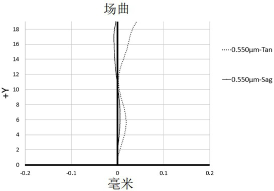
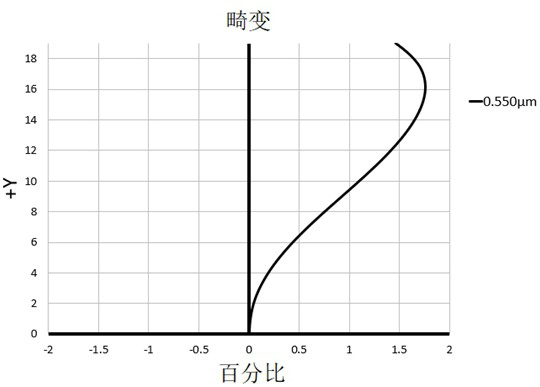
[0100] In this embodiment, the curves of field curvature, distortion, axial point spherical aberration and lateral chromatic aberration of the optical lens 200 are as follows Figure 7 , Figure 8 , Figure 9 and Figure 10 shown by Figure 7 to Figure 10 It can be seen that the f...

no. 3 example

[0102] see Figure 11 , which is a schematic structural view of the optical lens 300 provided in this embodiment, the structure of the optical lens 300 in this embodiment is roughly the same as that of the optical lens 100 in the first embodiment, the difference is that in this embodiment The radius of curvature and thickness of each lens of the optical mirror 300 are selected differently.

[0103] The relevant parameters of each lens in the optical lens provided in this embodiment are shown in Table 5.

[0104] table 5

[0105]

[0106] Table 6 shows the surface coefficients of each aspheric surface of the optical lens 300 in this embodiment.

[0107] Table 6

[0108]

[0109] In this embodiment, the curves of field curvature, distortion, axial point spherical aberration and lateral chromatic aberration of the optical lens 300 are as follows Figure 12 , Figure 13 , Figure 14 and Figure 15 shown by Figure 12 to Figure 15 It can be seen that the field curvatu...


PUM


Abstract

The invention discloses an optical lens and an imaging device. The optical lens sequentially comprises from the object side to the imaging surface along the optical axis: a first lens with positive optical power, the object side and the image side are both convex surfaces; The second lens with high degree, its object side and image side are both concave; stop; the third lens with positive power, its object side is concave, and the image side is convex; the fourth lens with negative power, its The object side is concave, and the image side is concave at the near optical axis; wherein, the first lens, the second lens, the third lens and the fourth lens are all aspherical lenses. The optical lens has the effect of telephoto macro, which can be used as a sub-macro lens in dual-camera or multi-camera, optimizing the imaging effect on the basis of conventional macro shooting; increasing the focal length of the lens increases the magnification, making shooting Macro produces a microscope-like effect.

Description

technical field [0001] The invention relates to the technical field of imaging lenses, in particular to an optical lens and imaging equipment. Background technique [0002] "Macro" means shooting at a relatively short distance with a large magnification. Human eyes often cannot see objects close to 15cm clearly, and the optical correction of professional macro lenses is designed according to the needs of close-up shooting. Microscopic objects such as bacteria and flowers can be photographed at close range, and images with a ratio of 1:1 or greater than 1 can be obtained; according to German industrial standards, those with an imaging ratio greater than 1:1 are in the category of macro photography. [0003] In recent years, the demand for macro photography by mobile phone users has been increasing, and the demand for miniaturized photographic lenses has been increasing day by day. However, the photosensitive devices of general photographic lenses are only charge-coupled devic...

Claims


Application Information

Patent Timeline
Patent Type & Authority Patents(China)
IPC IPC(8): G02B13/00G02B13/24G02B13/26G02B13/18
CPCG02B13/004G02B13/24G02B13/26G03B30/00
Inventor 章彬炜曾昊杰曾吉勇
Owner JIANGXI LIANYI OPTICS CO LTD
Why Eureka
Try Eureka