Eureka AIR delivers breakthrough ideas for toughest innovation challenges, trusted by R&D personnel around the world.

Steel belt cutting device and method

A technology of cutting device and steel strip, which is applied in the direction of shearing device, accessory device of shearing machine, device for cutting forming blank, etc. It can solve the problems of increasing production cost, increasing the frequency of motor maintenance, and limiting the position of steel strips of different widths, etc. problem, to achieve the effect of reducing the number of use, reducing the number of maintenance, and reducing the failure rate

Active Publication Date: 2021-09-21
无锡苏盛金属制品有限公司
View PDF7 Cites 0 Cited by
  • Summary
  • Abstract
  • Description
  • Claims
  • Application Information

AI Technical Summary

Problems solved by technology

[0002] The existing steel strip cutting machine is generally used to cut the steel strip, which can be cut into steel strips or steel blocks of different lengths. The existing steel strip cutting machine cannot be adjusted for steel strips of different widths. limit, so that it can move along a straight line and carry out cutting processing, and the existing steel strip cutting machine is generally equipped with multiple sets of motors, which increases the production cost and improves the number of motor maintenance. Therefore, we propose a steel strip cutting device and method to solve this problem

Method used


Image

  • Steel belt cutting device and method
  • Steel belt cutting device and method
  • Steel belt cutting device and method

Examples


Embodiment Construction

[0028] In order to make the technical means, creative features, goals and effects achieved by the present invention easy to understand, the present invention will be further described below in conjunction with specific embodiments.

[0029] In the description of the present invention, it should be noted that the terms "upper", "lower", "inner", "outer", "front end", "rear end", "both ends", "one end", "another end" The orientation or positional relationship indicated by etc. is based on the orientation or positional relationship shown in the drawings, and is only for the convenience of describing the present invention and simplifying the description, rather than indicating or implying that the referred device or element must have a specific orientation, use a specific Azimuth configuration and operation, therefore, should not be construed as limiting the invention. In addition, the terms "first" and "second" are used for descriptive purposes only, and should not be understood ...


PUM


Abstract

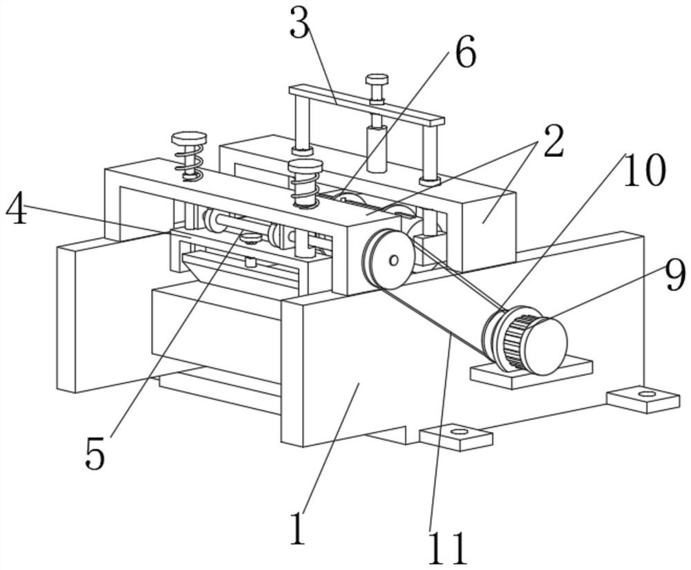
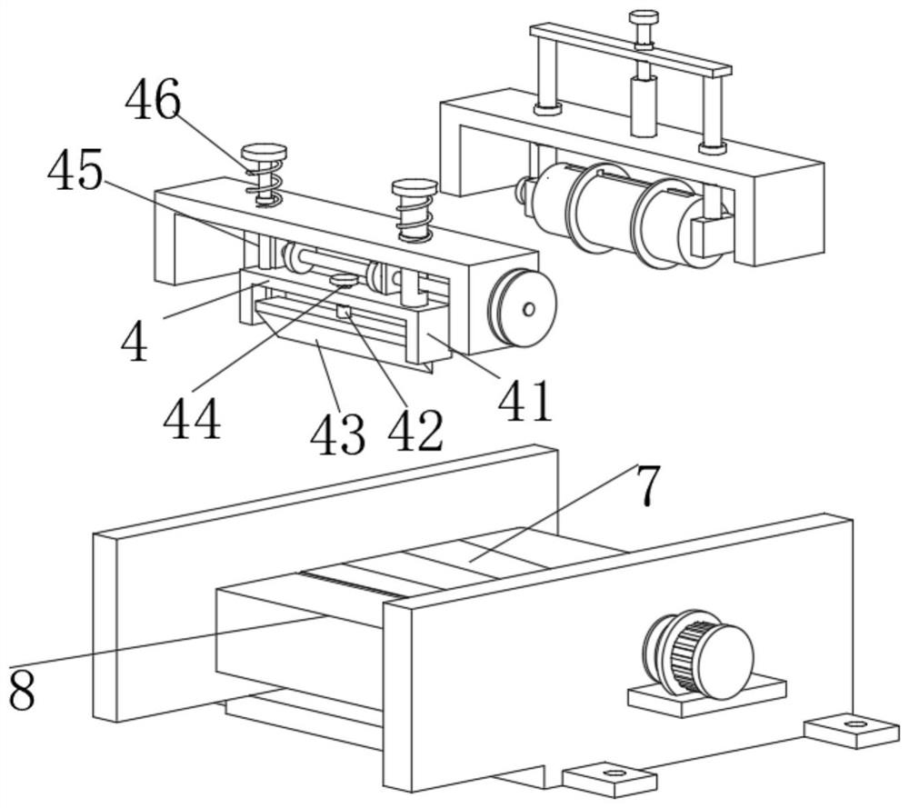
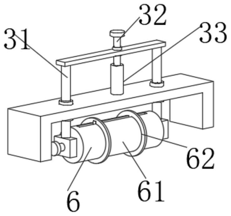
The invention discloses a steel belt cutting device and a method. The device comprises a mounting plate, wherein a connecting plate and a chain plate conveying belt are mounted in an inner cavity of the mounting plate, the chain plate conveying belt is driven by a driving motor, two U-shaped plates are arranged at the upper end of the mounting plate, a shearing assembly and a transmission assembly are installed on the U-shaped plate on the left side, the transmission assembly is connected with a driving wheel fixedly arranged on an output shaft of the driving motor through a belt, an adjusting assembly is installed on the U-shaped plate on the right side, and a limiting assembly is rotationally arranged on the adjusting assembly. According to the steel belt cutting device and the method, the device is provided with the adjusting assembly and the limiting assembly, two limiting rings can conduct limiting treatment on steel belts with different widths through cooperation of the adjusting assembly and the limiting assembly, a linear distance between a shear knife and the upper end of the connecting plate can be changed by rotating a first screw rod, the steel belt is cut into blocks with different lengths subsequently, and conveying and cutting treatment on the steel belt are achieved through a motor.

Description

technical field [0001] The invention relates to the field of steel strip cutting equipment, in particular to a steel strip cutting device and method. Background technique [0002] The existing steel strip cutting machine is generally used to cut the steel strip, which can be cut into steel strips or steel blocks of different lengths. The existing steel strip cutting machine cannot be adjusted for steel strips of different widths. limit, so that it moves along a straight line and performs cutting processing, and the existing steel strip cutting machine is generally equipped with multiple sets of motors, which increases the production cost and improves the number of motor maintenance. Therefore, we propose a steel strip cutting device and method to solve this problem. Contents of the invention [0003] The main purpose of the present invention is to provide a steel strip cutting device and method, which can effectively solve the problems in the background technology. [00...

Claims


Application Information

Patent Timeline
Patent Type & Authority Applications(China)
IPC IPC(8): B23D23/00B23D33/00
CPCB23D23/00B23D33/00
Inventor 顾沁羽严海军张海军沈俊杰
Owner 无锡苏盛金属制品有限公司
Why Eureka
Eureka Blog
Learn More