
Part defect detection method and device, medium and computer program product

A defect detection and parts technology, applied in the field of image processing, can solve problems such as low detection accuracy, and achieve the effect of improving the overall vision, improving the accuracy of defect detection, and improving reliability and accuracy

Active Publication Date: 2021-09-21
深圳市信润富联数字科技有限公司
View PDF8 Cites 11 Cited by
  • Summary
  • Abstract
  • Description
  • Claims
  • Application Information

AI Technical Summary

Problems solved by technology

[0003] The main purpose of this application is to provide a part defect detection method, equipment, medium and computer program product, aiming to solve the technical problem of low accuracy of part defect detection in the prior art

Method used


Image

  • Part defect detection method and device, medium and computer program product
  • Part defect detection method and device, medium and computer program product
  • Part defect detection method and device, medium and computer program product

Examples


Embodiment Construction

[0022] It should be understood that the specific embodiments described here are only used to explain the present application, not to limit the present application.

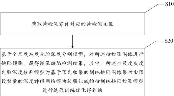
[0023] The embodiment of the present application provides a part defect detection method. In the first embodiment of the part defect detection method of the present application, refer to figure 1 , the part defect detection method includes:

[0024] Step S10, acquiring the image to be inspected corresponding to the part to be inspected;

[0025] In this embodiment, it should be noted that the image to be inspected is an X-ray image of the part to be inspected, wherein the X-ray image of the part to be inspected includes an X-ray image of an automobile steering knuckle and an X-ray image of an industrial casting Image and other images, the X-ray image of the automobile steering knuckle is a single-channel grayscale image, and the X-ray image of the automobile steering knuckle has relatively few types of defects, i...


PUM


Abstract

The invention discloses a part defect detection method and device, a medium and a computer program product. The part defect detection method comprises the steps of obtaining a to-be-detected image corresponding to a to-be-detected part, carrying out the defect prediction of the to-be-detected image based on a full-scale gray scale prior depth segmentation model, and obtaining an image defect detection result. The full-scale gray scale prior depth segmentation model is obtained by performing iterative training optimization on a to-be-trained defect detection model formed by cascading a preset number of deep neural network modules based on a pre-collected training defect image set. The technical problem that the defect detection accuracy of parts is low is solved.

Description

technical field [0001] The present application relates to the technical field of image processing, and in particular to a component defect detection method, equipment, medium and computer program product. Background technique [0002] With the development of modern industry, component defect detection technology is widely used in cloth defect detection, workpiece surface quality detection, aerospace and other fields. In the existing defect detection process of parts, many foundry companies still use more traditional detection methods, that is, after the parts are scanned and imaged in real time by X-rays, the corresponding negatives are physically printed out, and professional staff then inspect the parts. The image is manually inspected to determine the type of defect. However, using the traditional manual inspection method, there will be different inspectors due to their different inspection standards, which may lead to detection deviations, and people are prone to fatigue...

Claims


Application Information

Patent Timeline
Patent Type & Authority Applications(China)
IPC IPC(8): G06T7/00G06K9/34G06K9/62G06N3/04
CPCG06T7/0004G06T2207/10116G06N3/045G06F18/214
Inventor 于洋黄雪峰熊海飞
Owner 深圳市信润富联数字科技有限公司
Learn More