Stirring machine capable of calibrating non-uniform areas

A mixer and area technology, applied in the field of mixers that can calibrate uneven areas, can solve problems such as manual difficulty in finding, waste, and affecting the quality of final products

Inactive Publication Date: 2021-09-24
霍振伟
View PDF0 Cites 0 Cited by
  • Summary
  • Abstract
  • Description
  • Claims
  • Application Information

AI Technical Summary

Problems solved by technology

[0002] In the construction 3D printing industry and some laboratory scenarios, the quality of the mixture directly affects the quality of the final product, and small defects can also have serious consequences; and when the material is bonded and foreign matter is accidentally mixed into the material, facing the Tons of materials are often difficult to find and remove manually
Existing mixers lack foreign matter search and calibration devices. After sufficient long-term stirring, when the system judges that the uniformity is still unqualified, the mixed materials can only be discarded or manually rummaged for sticky matter or foreign matter, resulting in extreme big waste

Method used


Image

  • Stirring machine capable of calibrating non-uniform areas
  • Stirring machine capable of calibrating non-uniform areas
  • Stirring machine capable of calibrating non-uniform areas

Examples


Embodiment 1

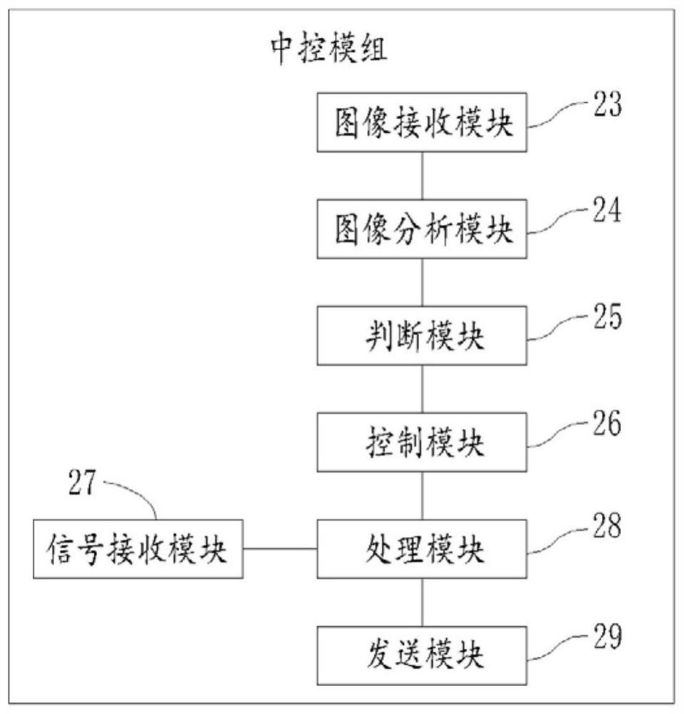
[0030] see figure 1 , in an embodiment of the present invention, a mixer, its structure includes: mixer housing 1, stirring motor 2, stirring blade 3, stirring shaft 4, central control module 5, discharge switch 6, discharge port 7, camera bracket 8. Camera fixing table 9 , camera 10 , display screen 11 , strain gauge group 15 , rotating shaft 16 , and image acquisition component 18 .

[0031] The stirring motor 2 is fixed on the mixer shell 1, and the stirring shaft 4 is connected to the shaft of the stirring motor 2; the stirring blade 3 is fixed on the stirring shaft 4, and the stirring blade 3 has a certain inclination angle, so as to stir the lower layer materials to the upper layer, and the materials The purpose of thorough mixing between.

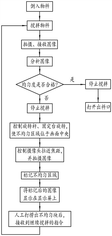
[0032] A strain gauge group 15 is installed on the stirring blade 3. When the stirring blade 3 touches a foreign object, it will deform briefly and slightly, resulting in a sudden change in the voltage of the strain gauge group 15. ...

Embodiment 2

[0043] The difference from the first embodiment is that after the uneven area in the material is analyzed, the uneven block is clamped out by a manipulator. Specifically:

[0044] Such as Figure 4 and Figure 5 As shown, the manipulator base 12 is installed on the mixer, the end of the manipulator 13 is equipped with a manipulator 14, and the manipulator 14 is connected to the manipulator 13 shafts, and the manipulator includes a gripper 19, a manipulator motor 20, a protective shell 22, and a mounting seat 21 , the manipulator motor 20 drives the jaws 19 to open and close, and the protective shell 22 is installed outside the manipulator motor 20 to protect the motor from bumping and prevent the motor from wading. The mounting base 21 is connected to the mechanical arm 13 by bolts, and the jaws 19 The mesh structure can effectively leak normal particle materials back into the mixer, and only filter out sticky matter and foreign matter, etc. The jaws 19 can be replaced flexi...


PUM


Abstract

The invention relates to the field of 3D printing stirring machines, and particularly discloses a stirring machine capable of calibrating non-uniform areas. The stirring machine comprises a stirring machine shell, an image acquisition component arranged on the stirring machine shell and a central control module connected with the image acquisition component, and the central control module analyzes images acquired by the image acquisition component and seeks and calibrates non-uniform areas in the images; and the image acquisition component comprises a camera fixing part and a camera mounted on the camera fixing part, and the camera is used for acquiring images of materials in the stirring machine shell. The stirring machine can calibrate and display areas where materials are non-uniform in the stirring process, and the problem that a small quantity of foreign substances and sticking substances in materials are difficult to find is solved.

Description

technical field [0001] The invention relates to the field of 3D printing mixers, in particular to a mixer capable of marking uneven areas. Background technique [0002] In the construction 3D printing industry and some laboratory scenarios, the quality of the mixture directly affects the quality of the final product, and small defects can also have serious consequences; and when the material is bonded and foreign matter is accidentally mixed into the material, facing the Tons of materials are often difficult to find and remove manually. Existing mixers lack foreign matter search and calibration devices. After sufficient long-term stirring, when the system judges that the uniformity is still unqualified, the materials mixed this time can only be discarded or manually rummaged for sticky matter or foreign matter, resulting in extreme Big waste. Contents of the invention [0003] The invention provides a mixer capable of marking uneven areas to solve the above technical pro...

Claims


Application Information

Patent Timeline
Patent Type & Authority Applications(China)
IPC IPC(8): B29C64/314B29C64/336B33Y40/00B33Y40/10
CPCB29C64/314B29C64/336B33Y40/00B33Y40/10
Inventor 霍振伟
Owner 霍振伟
Why Eureka
Try Eureka