Multi-core starting method based on shared space

A technology of sharing space and space, applied in the field of multi-core startup based on shared space, can solve the problems of not having the conditions for widespread application, high cost, small space occupied by startup programs, etc., saving hardware cost and volume, and low development cost. , the effect of easy transplantation

Active Publication Date: 2021-09-24
SHANDONG INST OF AEROSPACE ELECTRONICS TECH
View PDF7 Cites 1 Cited by
  • Summary
  • Abstract
  • Description
  • Claims
  • Application Information

AI Technical Summary

Problems solved by technology

However, some multi-core processors only integrate processors, and each processor still needs to configure the boot memory separately, as in figure 1 shown
Usually, the startup program of an embedded computer occupies a relatively small space, and the startup memory space is wasted a lot
On the other hand, military or aerospace memory is bulky and expensive, which hinders the further improvement of computer system integration and cost reduction design.
[0003] DSP6713J / 500 is a 4-core high-performance and high-reliability military processor. The processor currently supports two multi-core startup methods. One is the ROM startup method, which needs to be connected to a FLASH for each core. The core starts from the FLASH on the chip select CE1 memory. The second startup method is to use HPI to start. HPI startup requires two conditions. First, the processor must have an HPI interface, and second, add an FPGA outside the chip to simulate the HPI host through the FPGA. The host function starts multi-core through the HPI controller inside the FPGA. This method cannot be used for processors without an HPI interface. Therefore, the HPI method is only applicable to specific processors and does not have the conditions for widespread application.

Method used


Image

  • Multi-core starting method based on shared space
  • Multi-core starting method based on shared space
  • Multi-core starting method based on shared space

Examples


Embodiment Construction

[0021] In order to understand the above-mentioned purpose, features and advantages of the present invention more clearly, the present invention will be further described below in conjunction with the accompanying drawings and embodiments. Many specific details are set forth in the following description to facilitate a full understanding of the present invention. However, the present invention can also be implemented in other ways than those described here. Therefore, the present invention is not limited to the specific embodiments disclosed below.

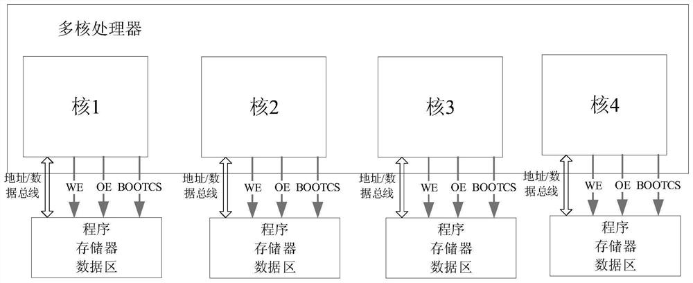
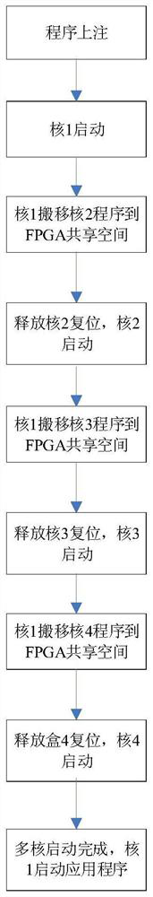
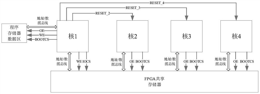
[0022] This program is a more economical and easy-to-implement multi-core software startup technology developed in the use of DSP6713J / 500 multi-core processors. This technology takes the DSP6713J / 500 multi-core processor control computer system as the application object, and supports loading the software of core 2, 3, and 4 through core 1, without configuring a separate FLASH memory for each core. It can save the cost and volume o...


PUM


Abstract

The invention discloses a multi-core starting method based on a shared space. The method comprises the following steps of: using an FPGA, hooking the FPGA in an IO space of a core 1, simultaneously hooking the FPGA in CE1 starting FLASH spaces of a core 2, a core 3 and a core 4; simulating the CE1 starting spaces of the cores 2, 3 and 4 through the FPGA, moving a starting program of the core 2 in the FLASH of the core 1 to a shared memory space of the FPGA after starting the core 1; releasing reset of the core 2, making the core 2 to start guide software; making the guide software of the core 2 interact with the core 1; moving application software to the internal RAM space of the FPGA through the shared space of the FPGA;starting the application software to run the application software; and implementing the starting process of the core 3 and the starting process of the core 4 as the above steps. According to the method, hardware cost and size are saved; and in addition, a three-bus interaction control mode of a processor is used. The method has the advantages of good universality, convenient transplantation, low software development cost and higher practical application value.

Description

technical field [0001] The invention belongs to the field of software starting methods, and in particular relates to a multi-core starting method based on a shared space. Background technique [0002] With the continuous development of processor integration technology, high-performance and highly integrated multi-core processors have been widely used. In the past, multiple computers can be integrated into one computer, and multi-core processors can be used instead of the original multiple computers to process different tasks. program. However, some multi-core processors only integrate processors, and each processor still needs to configure the boot memory separately, as in figure 1 shown. Usually, the startup program of an embedded computer takes up relatively little space, and the startup memory space is wasted a lot. On the other hand, military or aerospace memory has a large volume and high cost, which hinders the further improvement of computer system integration and ...

Claims


Application Information

Patent Timeline
Patent Type & Authority Applications(China)
IPC IPC(8): G06F3/06G06F9/445
CPCG06F3/0608G06F3/0629G06F3/0679G06F9/44505
Inventor 邱庆林高兰志李伟强杨将张毅
Owner SHANDONG INST OF AEROSPACE ELECTRONICS TECH
Why Eureka
Try Eureka