Lathe tool wear degree detection device convenient to mark

A lathe tool and detection device technology, applied in the direction of mechanical roughness/irregularity measurement, manufacturing tools, workshop equipment, etc., can solve the problem of no tool wear degree detection equipment, and achieve the effect of easy detection

Active Publication Date: 2021-09-28
西安良信精密机械有限公司
View PDF3 Cites 0 Cited by
  • Summary
  • Abstract
  • Description
  • Claims
  • Application Information

AI Technical Summary

Problems solved by technology

[0004] The object of the present invention is to provide a lathe tool wear detection device that can detect the degree of cutter head defect and the degree of wear of the cutter head

Method used


Image

  • Lathe tool wear degree detection device convenient to mark
  • Lathe tool wear degree detection device convenient to mark
  • Lathe tool wear degree detection device convenient to mark

Examples


Embodiment 1

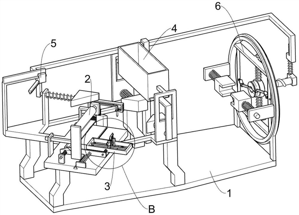
[0026] A lathe tool wear detection device that is convenient for marking, such as Figure 1-5 As shown, it includes a first fixed frame 1, a flatness test mechanism 2 and a wear degree test mechanism 3, and the first fixed frame 1 is provided with a flatness test mechanism 2, which is used to detect the flatness of the cutter head. The testing mechanism 2 is provided with a wear degree testing mechanism 3, and the wear degree testing mechanism 3 is used for detecting the wear degree of the cutter head.

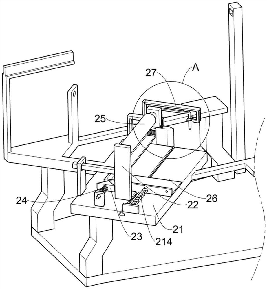
[0027]The flatness testing mechanism 2 includes a second fixed frame 21, a first sliding frame 22, a first wedge block 23, a first return spring 24, an electric push rod 25, a second sliding frame 26, a wedge frame 27, a wedge plate 28, The second return spring 29, the third sliding frame 211, the third return spring 212, the first marking pen 213 and the tension spring 214, the second fixed frame 21 is fixedly installed on the first fixed frame 1, and the first sliding frame ...

Embodiment 2

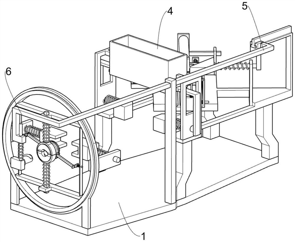
[0033] On the basis of Example 1, such as Image 6 As shown, a cooling mechanism 4 is also included. The cooling mechanism 4 is arranged on the second fixed frame 21. The cooling mechanism 4 is used to cool the cutter head. The cooling mechanism 4 includes a fifth fixed frame 41, a second wedge 42, a second Seven return springs 43, the sixth fixed mount 44 and the fixed frame 45, the fifth fixed mount 41 are symmetrically welded on the second fixed mount 21, the fifth fixed mount 41 is slidably connected with the second wedge block 42, the second wedge block 42 is used for clamping the tool, the second wedge block 42 is fixedly connected with the seventh return spring 43, one end of the seventh return spring 43 away from the second wedge block 42 is connected with the fifth fixed frame 41, and the sixth fixed frame 44 is welded At one end of the second wedge block 42, a fixed frame 45 is jointly supported above the two fifth fixed frames 41, the sixth fixed frame 44 is slidabl...

Embodiment 3

[0036] On the basis of Example 2, such as Figure 6-8 As shown, a reciprocating mechanism 5 is also included, and the reciprocating mechanism 5 is slidably connected on the second fixed frame 21. The reciprocating mechanism 5 includes a third wedge block 51, an eighth return spring 52, a seventh fixed frame 53 and a sixth sliding frame. frame 54, the third wedge block 51 is slidably connected to the second fixed frame 21, the third wedge block 51 is fixedly connected with the eighth return spring 52, one end of the eighth return spring 52 away from the third wedge block 51 and the second The fixed frame 21 is connected, and one end of the third wedge block 51 close to the second fixed frame 21 is welded with a seventh fixed frame 53, and the seventh fixed frame 53 is used to push the sixth sliding frame 54 to move away from the first sliding frame 22. The second fixed frame 21 is slidably connected with a sixth sliding frame 54 , the sixth sliding frame 54 is slidably connecte...


PUM


Abstract

The invention relates to a lathe tool wear degree detection device, in particular to a lathe tool wear degree detection device convenient to mark. The lathe tool wear degree detection device convenient to mark comprises a first fixing frame, a flatness testing mechanism, a wear degree testing mechanism and the like, The flatness testing mechanism is arranged on the first fixing frame, and the wear degree testing mechanism is arranged on the flatness testing mechanism. A wedge-shaped frame pushes a third sliding frame and a first marking pen to move downwards, the first marking pen marks a damaged part of a tool bit, grinding of the tool bit in the later period is facilitated, the depth of a worn part of the tool bit marked by the first marking pen can be known according to the movement stroke of a wedge-shaped plate and a device on the wedge-shaped plate, and therefore the defect degree of the tool bit is judged.

Description

technical field [0001] The invention relates to a device for detecting the degree of wear of a lathe tool, in particular to a device for detecting the degree of wear of a lathe tool which is convenient for marking. Background technique [0002] The turning tool is a tool with one cutting part for turning. The turning tool is one of the most widely used tools in cutting. The working part of the turning tool is the part that generates and processes chips, including the cutting edge, breaking chips Structural elements such as the broken or rolled structure, the space for chip removal or chip storage, the passage of cutting fluid, etc. Turning tools are used on various lathes to process outer circles, inner holes, end faces, threads, grooves, etc. [0003] After a long time of use of the turning tool, the tool head will be worn out. The tool head wear will weaken the safety of the turning process, which will easily cause the lathe to stop unexpectedly, resulting in waste of blad...

Claims


Application Information

Patent Timeline
IPC IPC(8): B23Q17/09
CPCB23Q17/09B25H7/04G01B5/28B23Q2717/003Y02P70/10
Inventor 胡祥
Owner 西安良信精密机械有限公司
Why Eureka
Try Eureka