
Broken hair removing equipment for processing disc brush

A disc brush and equipment technology, which is applied in metal processing and other directions, can solve the problems of mixed hairs and poor effect of removing hairs, and achieve the effect of improving stability and reducing labor intensity

Active Publication Date: 2021-09-28
安徽环美刷业股份有限公司
View PDF11 Cites 0 Cited by
  • Summary
  • Abstract
  • Description
  • Claims
  • Application Information

AI Technical Summary

Problems solved by technology

[0003]The hair suction device in the prior art usually directly uses the suction fan to suck out the broken hairs, but some of the broken hairs are mixed in the bristles of the disc brush, and it is difficult to suck them out through the suction fan. Leads to less effective hair removal

Method used


Image

  • Broken hair removing equipment for processing disc brush
  • Broken hair removing equipment for processing disc brush
  • Broken hair removing equipment for processing disc brush

Examples


Embodiment 1

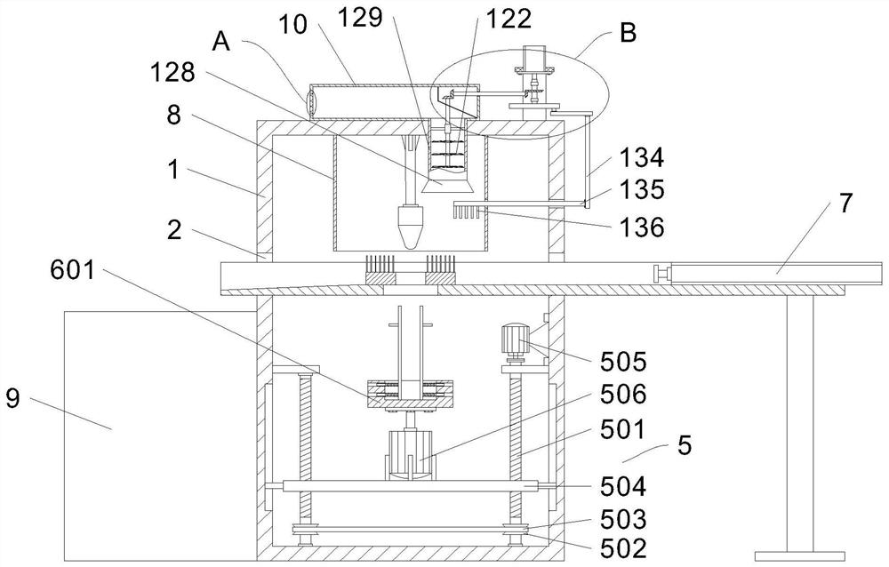
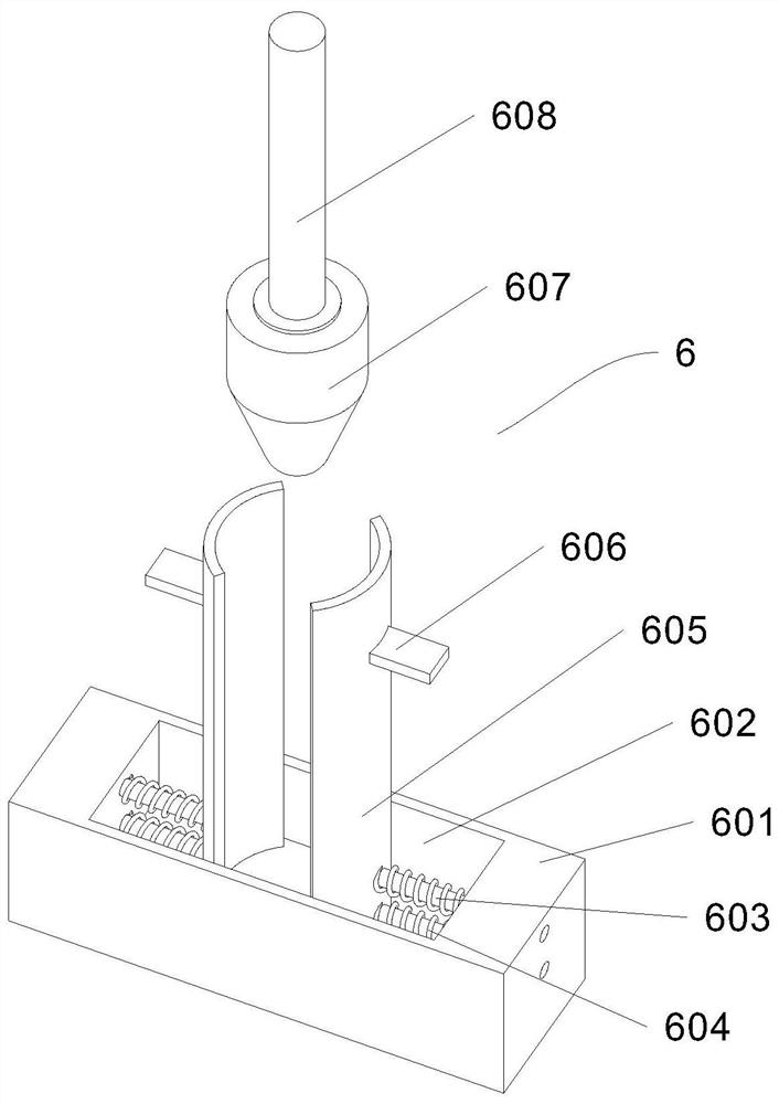
[0030] In this embodiment, as shown in Figures 1-5, a kind of delinting equipment for disc brush processing includes a box body 1 with an incompletely closed front end, a side door is provided at the front end of the box body 1, and a removable Viewing window, the upper part of both side walls of the box body 1 is provided with a port 2, and a loading case 3 for placing a disc brush is fixed between the two openings 2, and the loading case 3 is close to the bottom of the side section of the collection box 9 It is inclined, and the load case 3 is provided with a through groove 4, and the side section of the load case 3 outside the box 1 is fixed with a hydraulic rod 7, and the telescopic end of the hydraulic rod 7 is fixed with a push block. The outer end is located below the end of the loading shell 3 away from the hydraulic rod 7, and a collection box 9 is provided, and a rotary lifting mechanism 5 is provided below the through groove 4 in the box body 1, and a rotary lifting ...

Embodiment 2

[0034] On the basis of Embodiment 1, the inner wall of the temporary storage box 10 is fixed with a protective plate 18 to prevent the broken hairs from entering between the bevel gear one 123 and the bevel gear two 124, so as to avoid the broken hairs from being entangled in the bevel gear one 123 and the bevel gear two 124 and cause damage. The upper parts of the outer ends of the two splints 605 are fixed with a limiting plate 606 to prevent the disc brush from shifting downward, that is, the bottom end of the disc brush abuts against the top of the limiting plate 606 to improve the stability of the disc brush when rotating.

Embodiment 3

[0036] On the basis of embodiment 2, carding mechanism 13 comprises the circular plate 131 that is fixed on the bottom end of rotating shaft three 17, and the bottom end of circular plate 131 is fixed with eccentric rod 132, and the bottom end of eccentric rod 132 is rotatably connected with rotating rod 133, and rotating rod One side of the bottom end of 133 is rotatably connected with a vertical bar 134, and one end of the vertical bar 134 close to the casing 1 is fixed with a cross bar 135 below the suction hood 128, and the bottom end of the cross bar 135 is fixed at a position in the housing 8. A plurality of picks 136 for poking the bristles of the disc brush. Through the above method, the rotating shaft 3 17 rotates, drives the circular plate 131 to rotate, and then drives the eccentric rod 132 to rotate, thereby driving the rotating rod 133 to move, driving the vertical rod 134 connected to the rotating rod 133 to move, thereby driving the horizontal rod 135 to reciproc...


PUM


Abstract

The invention relates to the field of processing of disc brushes, in particular to broken hair removing equipment for processing a disc brush. The broken hair removing equipment comprises a box body; a position, below a through groove, in the box body is provided with a rotary lifting mechanism; a clamping mechanism is arranged above the rotary lifting mechanism; a shell is fixed to a position, corresponding to the through groove, of a top wall of the box body; a temporary storage box used for storing broken hair is fixed to a top end of the box body; an absorption mechanism is arranged on the box body; and a teasing mechanism is arranged on the box body. The broken hair removing equipment provided by the invention is additionally provided with the rotary lifting mechanism, the clamping mechanism, the absorption mechanism, the teasing mechanism and the like, wherein the rotary lifting mechanism drives a clamping plate to move upwards; then the clamping mechanism clamps a disc brush; the rotary lifting mechanism continues to drive the disc brush to move upwards and make contact with the teasing mechanism; the disc brush rotates; a motor III is started; the teasing mechanism stirs bristles of the disc brush, and meanwhile the absorption mechanism absorbs the broken hair mixed in the disc brush into the temporary storage box for storage; broken hair can be removed well; and the quality of the disc brush is guaranteed.

Description

technical field [0001] The invention relates to the technical field of disc brush processing, in particular to a hair removal device for disc brush processing. Background technique [0002] The application range of the brush covers almost all industries. Its main purpose is cleaning, dust removal, polishing, etc. during the production process. During the processing of the disc brush, the bristles need to be trimmed to make the bristles highly consistent. When trimming the bristles, part of the broken hairs will get into the bristles of the disc brush and need to be sucked out by the suction device. [0003] The hair suction device in the prior art usually directly uses the suction fan to suck out the broken hairs, but some of the broken hairs are mixed in the bristles of the disc brush, and it is difficult to suck them out through the suction fan, resulting in poor effect of removing the broken hairs. For this reason, we have proposed a kind of deburring equipment for disc ...

Claims


Application Information

Patent Timeline
Patent Type & Authority Applications(China)
IPC IPC(8): B26D7/18
CPCB26D7/1863B26D7/18B26D2007/1809
Inventor 许学娟徐华海周乾汪鲁平方润泽华凯
Owner 安徽环美刷业股份有限公司
Learn More