Wire spool device for optical fiber manufacturing and capable of avoiding disordered winding

A winding reel and chaotic technology, which is applied in the field of winding reel devices for optical fiber manufacturing, can solve the problems of imperfect structure of the winding reel, unreasonable control of the winding speed, and affecting the quality of the winding, so as to avoid damage to the wire after drawing Optical fiber, easy to adjust the effect of winding speed

Inactive Publication Date: 2021-09-28
厦门遂宝贸易有限公司
View PDF0 Cites 0 Cited by
  • Summary
  • Abstract
  • Description
  • Claims
  • Application Information

AI Technical Summary

Problems solved by technology

[0005] Aiming at the deficiencies of the prior art, the present invention provides a winding reel device for optical fiber manufacturing that avoids winding chaos, which can avoid winding quality after fiber drawing and facilitate adjustment of winding speed to avoid damage to the drawn optical fiber etc. It solves the problem that the optical fiber needs to be wound into a coil after wire drawing. The structure of the existing optical fiber winding device is not perfect, and there is confusion in the winding process, that is, the optical fiber is randomly wound on the coil , which seriously affects the quality of winding, and the existing winding device after fiber drawing cannot adjust the winding speed, and cannot reasonably control the winding speed, which may cause damage to the fiber during winding

Method used


Image

  • Wire spool device for optical fiber manufacturing and capable of avoiding disordered winding
  • Wire spool device for optical fiber manufacturing and capable of avoiding disordered winding
  • Wire spool device for optical fiber manufacturing and capable of avoiding disordered winding

Examples


Embodiment 1

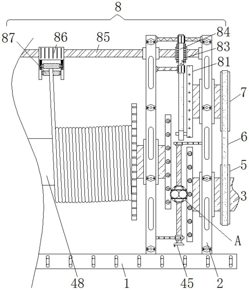
[0029] A winding reel device for optical fiber manufacturing that avoids winding confusion, including a base 1, the top of the base 1 is fixedly connected with a fixed plate 2, the inside of the fixed plate 2 is movably connected with a drive shaft 3, and the right side of the drive shaft 3 is fixedly connected There is a drive motor, which is not specifically shown in the figure. The left side of the drive shaft 3 is fixedly connected with a speed regulating mechanism 4, the outer wall of the drive shaft 3 is fixedly connected with a drive disc 5, and the bottom of the drive disc 5 is connected with a belt 6. A driven disc 7 is connected to the side away from the drive disc 5. The shape and size of the driven disc 7 are the same as that of the drive disc 5, and the driven disc 7 is directly above the drive disc 5, and the left side of the driven disc 7 is fixed. A guide mechanism 8 is connected.

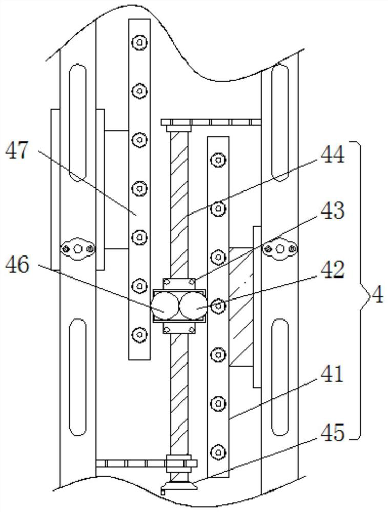
[0030] The inside of the speed regulating mechanism 4 is provided with a first ...

Embodiment 2

[0032] A winding reel device for optical fiber manufacturing that avoids winding confusion, including a base 1, the top of the base 1 is fixedly connected with a fixed plate 2, the inside of the fixed plate 2 is movably connected with a drive shaft 3, and the right side of the drive shaft 3 is fixedly connected There is a drive motor, which is not specifically shown in the figure. The left side of the drive shaft 3 is fixedly connected with a speed regulating mechanism 4, the outer wall of the drive shaft 3 is fixedly connected with a drive disc 5, and the bottom of the drive disc 5 is connected with a belt 6. A driven disc 7 is connected to the side away from the drive disc 5. The shape and size of the driven disc 7 are the same as that of the drive disc 5, and the driven disc 7 is directly above the drive disc 5, and the left side of the driven disc 7 is fixed. A guide mechanism 8 is connected.

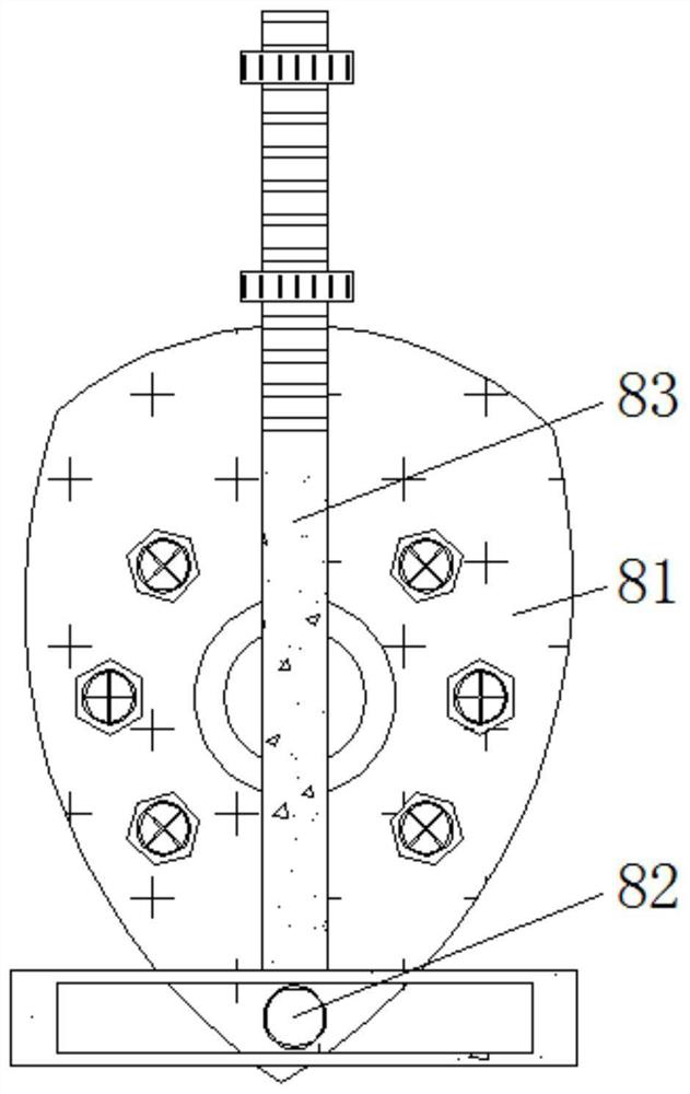
[0033] The inside of the guide mechanism 8 is provided with a cam 81, the right...

Embodiment 3

[0035] A winding reel device for optical fiber manufacturing that avoids winding confusion, including a base 1, the top of the base 1 is fixedly connected with a fixed plate 2, the inside of the fixed plate 2 is movably connected with a drive shaft 3, and the right side of the drive shaft 3 is fixedly connected There is a drive motor, which is not specifically shown in the figure. The left side of the drive shaft 3 is fixedly connected with a speed regulating mechanism 4, the outer wall of the drive shaft 3 is fixedly connected with a drive disc 5, and the bottom of the drive disc 5 is connected with a belt 6. A driven disc 7 is connected to the side away from the drive disc 5. The shape and size of the driven disc 7 are the same as that of the drive disc 5, and the driven disc 7 is directly above the drive disc 5, and the left side of the driven disc 7 is fixed. A guide mechanism 8 is connected.

[0036]The inside of the speed regulating mechanism 4 is provided with a first r...


PUM


Abstract

The invention relates to the technical field of optical fiber manufacturing, and discloses a wire spool device for optical fiber manufacturing and capable of avoiding disordered winding, which comprises a base, the top of the base is fixedly connected with a fixing plate, a driving shaft is movably connected in the fixing plate, the left side of the driving shaft is fixedly connected with a speed regulating mechanism, and the outer wall of the driving shaft is fixedly connected with a driving disc. According to the wire spool device for optical fiber manufacturing and capable of avoiding disordered winding, the driving shaft rotates, at the moment, a cam can also rotate, a rolling shaft is further made to periodically move left and right, at the moment, the rolling shaft can drive the drawn optical fiber to periodically wind left and right, and therefore the effect that the winding quality is prevented from being affected by disordered wire winding after optical fiber drawing is achieved. A rotary knob is rotated, the transmission ratio between a second rotating disc and a first rotating disc is further changed, at the moment, the rotating speed of a winding roller is also changed, and therefore the effects that the winding speed is conveniently adjusted, and the drawn optical fiber is prevented from being damaged are achieved.

Description

technical field [0001] The invention relates to the technical field of optical fiber manufacturing, in particular to a winding reel device for optical fiber manufacturing that avoids winding confusion. Background technique [0002] Optical fiber is a kind of fiber made of glass or plastic, which can be used as a light transmission tool. The process of making optical fiber from raw materials such as silicon tetrachloride is optical fiber manufacturing. The process of optical fiber manufacturing determines the mechanical strength, transmission characteristics and use of optical fiber. Life is very important to ensure the quality of optical fiber. The manufacture of communication optical fiber is divided into two processes: rod making and wire drawing. [0003] The optical fiber needs to be wound into a coil after drawing. The structure of the existing optical fiber winding device is not perfect. The quality of the fiber, and the existing winding device after fiber drawing ca...

Claims


Application Information

Patent Timeline
IPC IPC(8): B65H54/28B65H54/74
CPCB65H54/2809B65H54/74B65H2403/80B65H2407/30B65H2701/32
Inventor 潘紫婷
Owner 厦门遂宝贸易有限公司
Why Eureka
Try Eureka