Supercharge Your Innovation With Domain-Expert AI Agents!

Door system with door presenter control

An opener, door system technology, applied in the field of power door systems, that can solve problems such as damage, high stress, still in the open position or not fully returned to the non-deployed position of the opener

Pending Publication Date: 2021-09-28
MAGNA CLOSURES INC
View PDF10 Cites 0 Cited by
  • Summary
  • Abstract
  • Description
  • Claims
  • Application Information

AI Technical Summary

Problems solved by technology

While the above opener assemblies may prove effective in moving a vehicle closure panel to the open position, such opener assemblies have some potential disadvantages
[0009] Another disadvantage of known opener assemblies relates to the high reduction gearing required in conjunction with generating sufficient force to move the vehicle closure panel to the open position, especially when ice is expected to restrict the vehicle closure panel from the fully closed position of the vehicle closure panel areas of movement in combination with the high reduction gear
Although high reduction gears are generally effective at generating the high forces required to move a vehicle closure panel to the open position, high reduction gears cannot be driven back quickly
In this way, in the event that the vehicle closure panel is suddenly and quickly moved back from the open position towards the fully closed position, such as by a user slamming the door or in windy conditions, while the opener is still in the open position or not fully returned to the opener High reduction gears and components associated with high reduction gears can be highly stressed and damaged when in the non-deployed position

Method used


Image

  • Door system with door presenter control
  • Door system with door presenter control
  • Door system with door presenter control

Examples


Embodiment Construction

[0081] In the following description, details are set forth to provide an understanding of the present disclosure. In some instances, certain circuits, structures and techniques have not been described or shown in detail in order not to obscure the disclosure.

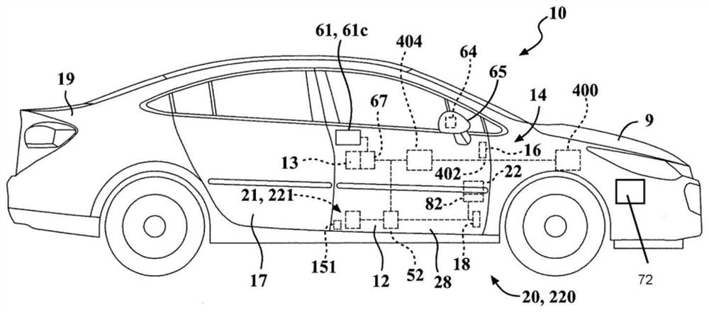
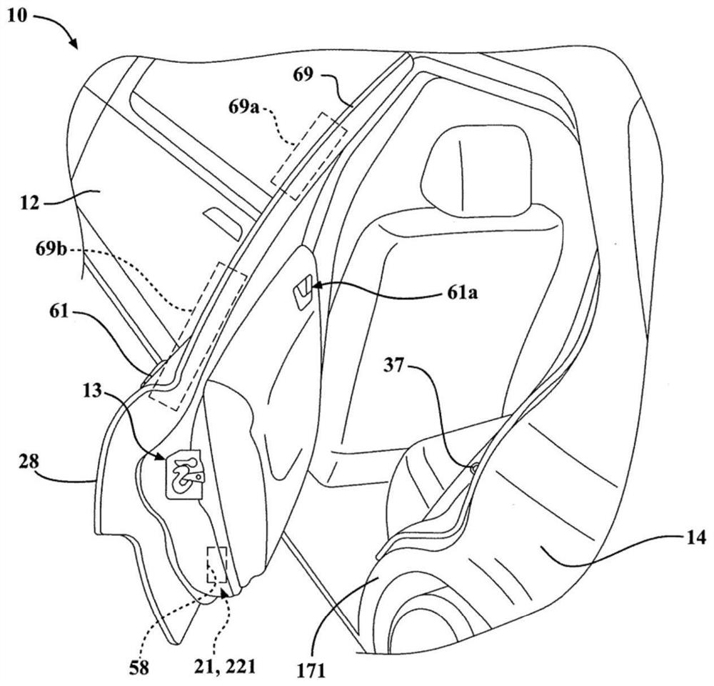
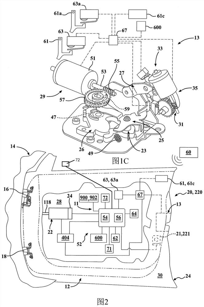
[0082] In general, a power door actuation system constructed in accordance with the teachings of the present disclosure, a closure panel for a vehicle door illustrated as a door module, and a power-operated door opener assembly, also referred to as an opener assembly, will now be described with reference to the accompanying drawings. An exemplary embodiment of the power-operated door opener assembly having a clutch unit also referred to as a clutch assembly is described more fully.

[0083] One or more exemplary embodiments are provided so that this disclosure will be thorough, and will fully convey the scope of the invention to those skilled in the art. Numerous specific details are set forth, such as examples of spec...


PUM


Abstract

A door system, a presenter assembly and a method for controlling movement of a motor vehicle closure panel between a closed position, a presented position and an open position are provided. The presenter assembly includes an electric motor having a drive shaft that extends along a drive shaft axis. A clutch assembly has an engaged state when electric motor is energized and a disengaged state when electric motor is de-energized. A presenter unit has a presenter lead screw and an extensible member configured for movement between a retracted position corresponding to the closed position and an extended position corresponding to the presented position. Extensible member is biased toward the retracted position by a presenter biasing member. The presenter lead screw is rotatably driven by the output member when electric motor is energized and when clutch assembly is in the engaged state to move the extensible member against the bias of the presenter biasing member to the extended position. The extensible member is automatically biased from the extended position to the retracted position by the presenter biasing member when the electric motor is de-energized and when the clutch assembly is in the disengaged state.

Description

[0001] Cross References to Related Applications [0002] This application claims the benefit of U.S. Provisional Application Serial No. 62 / 033,079, filed June 1, 2020, and U.S. Provisional Application Serial No. 62 / 993,981, filed March 24, 2020, both U.S. Provisional Applications The entire content of is incorporated herein by reference. technical field [0003] The present disclosure generally relates to power door systems for motor vehicles. More particularly, the present disclosure relates to a power door actuation system equipped with a power door opener assembly operable for powered movement of a vehicle door relative to a vehicle body from a closed position toward an open position. Background technique [0004] This section provides background information related to the present disclosure which is not necessarily prior art. [0005] In view of the increased consumer demand for motor vehicles equipped with advanced comfort and convenience features, many modern vehicle...

Claims


Application Information

Patent Timeline
IPC IPC(8): E05F15/622E05F15/70E05F15/71E05B81/06E05B81/18E05B81/56E05B83/36E05B77/02E05B77/34
CPCE05F15/622E05F15/70E05F15/71E05B81/06E05B81/18E05B81/56E05B83/36E05B77/02E05B77/34E05Y2201/216E05Y2900/531E05Y2201/434E05Y2201/426E05Y2201/218E05Y2800/428E05B81/64E05B81/76E05B81/14E05B81/20E05Y2400/3015E05Y2400/3013E05B81/54
Inventor 弗朗切斯科·昆博阿瑟·J·W·黑内什
Owner MAGNA CLOSURES INC
Features
  • R&D
  • Intellectual Property
  • Life Sciences
  • Materials
  • Tech Scout
  • Unparalleled Data Quality
  • Higher Quality Content
  • 60% Fewer Hallucinations
Learn More