

Voltage measuring circuit, method and equipment
A voltage measurement circuit and voltage measurement technology, applied in the direction of measuring electrical variables, measuring current/voltage, measuring devices, etc., can solve problems such as incorrect calculation, increased measurement voltage, and incorrect calculation results
- Summary
- Abstract
- Description
- Claims
- Application Information
AI Technical Summary
Problems solved by technology
Method used
Image

Examples
Embodiment Construction
[0031] In order to facilitate the understanding of the present application, the present application will be described more fully below with reference to the relevant drawings. Preferred embodiments of the application are shown in the accompanying drawings. However, the present application can be embodied in many different forms and is not limited to the embodiments described herein. On the contrary, the purpose of providing these embodiments is to make the understanding of the disclosure of the application more thorough and comprehensive.
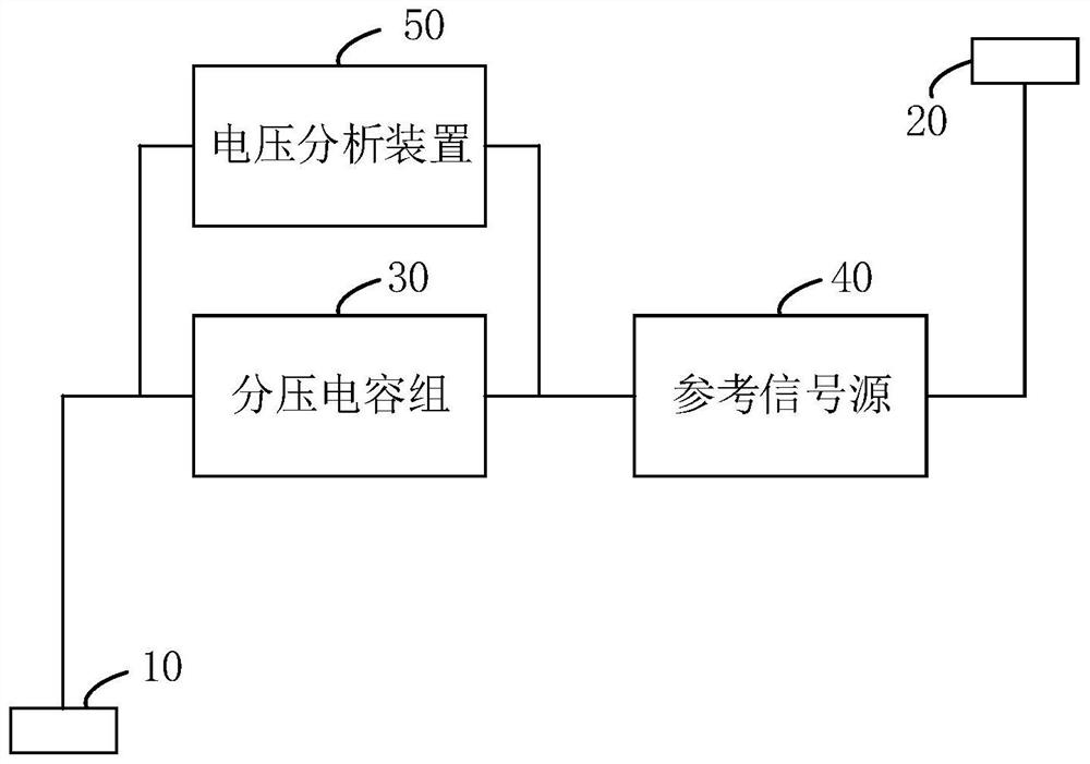
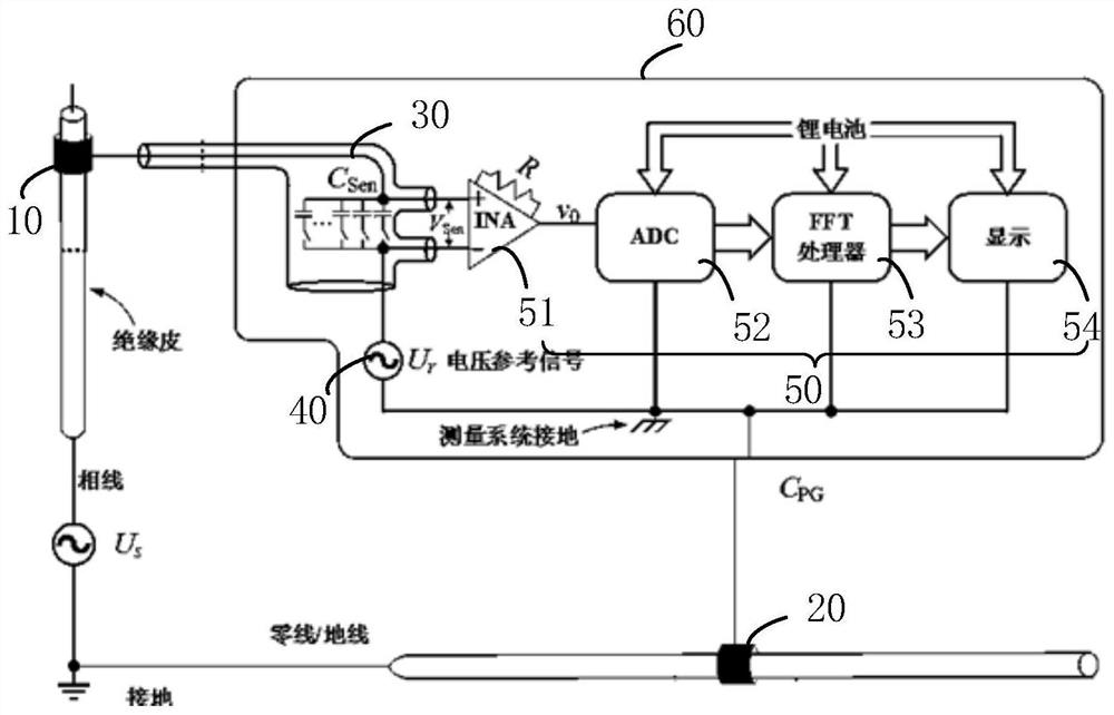
[0032] see figure 1 , a voltage measurement circuit, comprising: a first coupling device 10; a second coupling device 20, used to electrically couple the conductor to be measured into the voltage measurement circuit together with the first coupling device 10; a voltage dividing capacitor group 30, the first The coupling device 10 is connected to the first end of the voltage dividing capacitor group 30; the reference signal source 40, the ...
PUM
 Abstract
Description
Claims
Application Information