Fireproof heat dissipation structure of electrical automation equipment

A technology of electrical automation and heat dissipation structure, which is applied in the direction of electrical equipment construction parts, electrical components, and support structure installation, etc. It can solve the damage of components of electrical automation equipment, poor safety performance of electrical automation equipment, and affect the service life of electrical automation equipment, etc. problem, to achieve good safety performance and improve safety

Pending Publication Date: 2021-09-28
刘明
View PDF14 Cites 0 Cited by
  • Summary
  • Abstract
  • Description
  • Claims
  • Application Information

AI Technical Summary

Problems solved by technology

[0003] The purpose of the present invention is to provide a fire-proof and heat-dissipating structure for electrical automation equipment, which has the advantages of good safety performance, and solves the problem of poor safety performance of electrical automation equipment during use. If the electrical automation equipment causes a fire due to a line failure, users cannot Extinguish it in time, and most electrical automation equipment uses fans to dissipate heat inside. The disadvantage is that the fan directly blows cold air to the inside of the electrical automation equipment, which is easy to cause damage to the components of the electrical automation equipment, thus affecting the use of electrical automation equipment The problem of longevity

Method used


Image

  • Fireproof heat dissipation structure of electrical automation equipment
  • Fireproof heat dissipation structure of electrical automation equipment
  • Fireproof heat dissipation structure of electrical automation equipment

Examples


Embodiment Construction

[0025] The following will clearly and completely describe the technical solutions in the embodiments of the present invention with reference to the accompanying drawings in the embodiments of the present invention. Obviously, the described embodiments are only some, not all, embodiments of the present invention. Based on the embodiments of the present invention, all other embodiments obtained by persons of ordinary skill in the art without making creative efforts belong to the protection scope of the present invention.

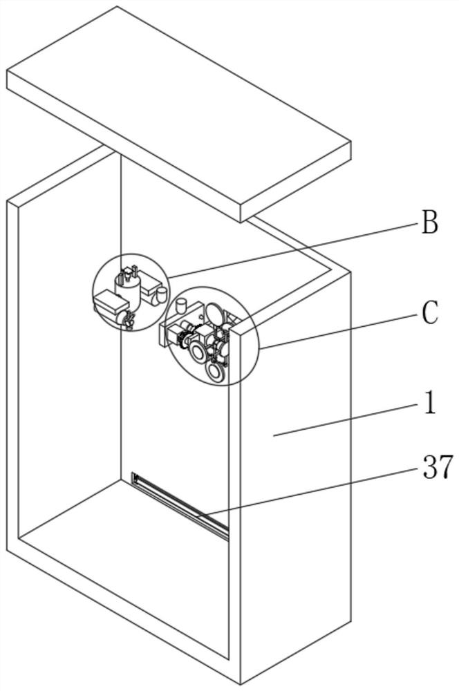
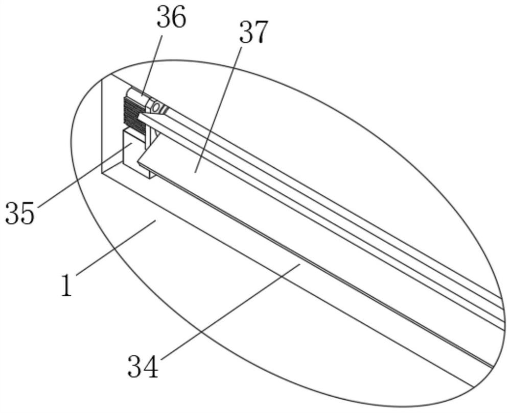
[0026] as attached figure 1 to attach Figure 9As shown: the present invention provides a fireproof and heat dissipation structure for electrical automation equipment, including electrical automation equipment 1, the bottom of both sides of the electrical automation equipment 1 is provided with a through groove 34, and the rear side of the inner cavity bottom of the through groove 34 is fixedly connected with a mounting Seat 35, the top of mounting seat 35 is...


PUM


Abstract

The invention relates to the technical field of electrical automation equipment, in particular to a fireproof heat dissipation structure of electrical automation equipment. The structure comprises the electrical automation equipment; exhaust holes are formed in two sides of the electrical automation equipment; inner cavities of the exhaust holes are filled with filter screens. Through cooperative use of the exhaust holes, a first electric telescopic rod, a vertical rod, a shell, a carrying plate, a toothed plate, an adjusting gear, a connecting rod, a fixing plate, a high-pressure carbon dioxide storage tank and an electromagnetic valve, the effect of extinguishing fire in the electrical automation equipment is achieved; through cooperative use of a bearing plate, a second electric telescopic rod, a fixed seat, a sliding rod, a driven gear, a fixed block, a circular plate, a motor I, a driving gear, a transmission rod I, a rotating seat I, a transmission rod II, a rotating rod, an exhaust plate, a heat conducting sheet and a rotating seat II, the effect of cooling the interior of the electrical automation equipment is achieved; and therefore, the safety of the electrical automation equipment is improved.

Description

technical field [0001] The invention relates to the technical field of electrical automation equipment, in particular to a fireproof and heat dissipation structure of electrical automation equipment. Background technique [0002] The safety performance of electrical automation equipment is poor when it is in use. If the electrical automation equipment causes a fire due to a line failure, the user cannot extinguish it in time, and most electrical automation equipment uses fans to dissipate heat inside. Air blowing into the interior of the electrical automation equipment can easily cause damage to the components of the electrical automation equipment, thus affecting the service life of the electrical automation equipment. In order to solve the above problems, a fire-proof and heat-dissipating structure for electrical automation equipment needs to be developed urgently. Contents of the invention [0003] The purpose of the present invention is to provide a fire-proof and heat...

Claims


Application Information

Patent Timeline
Patent Type & Authority Applications(China)
IPC IPC(8): H05K7/20H05K7/14
CPCH05K7/20145H05K7/14
Inventor 刘明
Owner 刘明
Why Eureka
Try Eureka