
Linear conveying device

A technology of linear conveying and conveying tracks, which is applied in the field of industrial manufacturing, can solve problems such as low production efficiency, large parts size, and high labor intensity, and achieve the effects of improving efficiency, high-speed conveying, and stable conveying

Pending Publication Date: 2021-10-01
GUANGZHOU MINO AUTOMOTIVE EQUIP CO LTD
View PDF0 Cites 1 Cited by
  • Summary
  • Abstract
  • Description
  • Claims
  • Application Information

AI Technical Summary

Problems solved by technology

However, at present, for large parts, such as bus bodies, due to the large size of the parts, traditional manual pushing is usually used, resulting in low production efficiency and high labor intensity

Method used


Image

  • Linear conveying device
  • Linear conveying device
  • Linear conveying device

Examples


Embodiment Construction

[0030] Embodiments of the present invention are described in detail below, examples of which are shown in the drawings, wherein the same or similar reference numerals designate the same or similar elements or elements having the same or similar functions throughout. The embodiments described below by referring to the figures are exemplary only for explaining the present invention and should not be construed as limiting the present invention.

[0031] In the description of the present invention, it should be understood that the orientation descriptions, such as up, down, front, back, left, right, etc. indicated orientations or positional relationships are based on the orientations or positional relationships shown in the drawings, and are only In order to facilitate the description of the present invention and simplify the description, it does not indicate or imply that the device or element referred to must have a specific orientation, be constructed and operated in a specific ...


PUM


Abstract

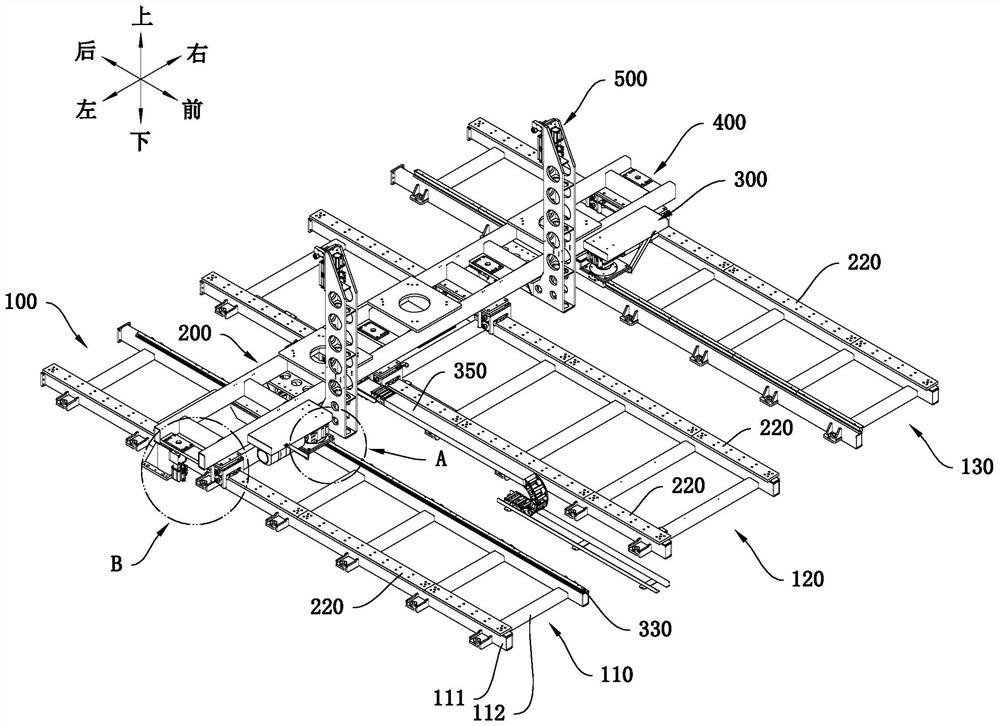
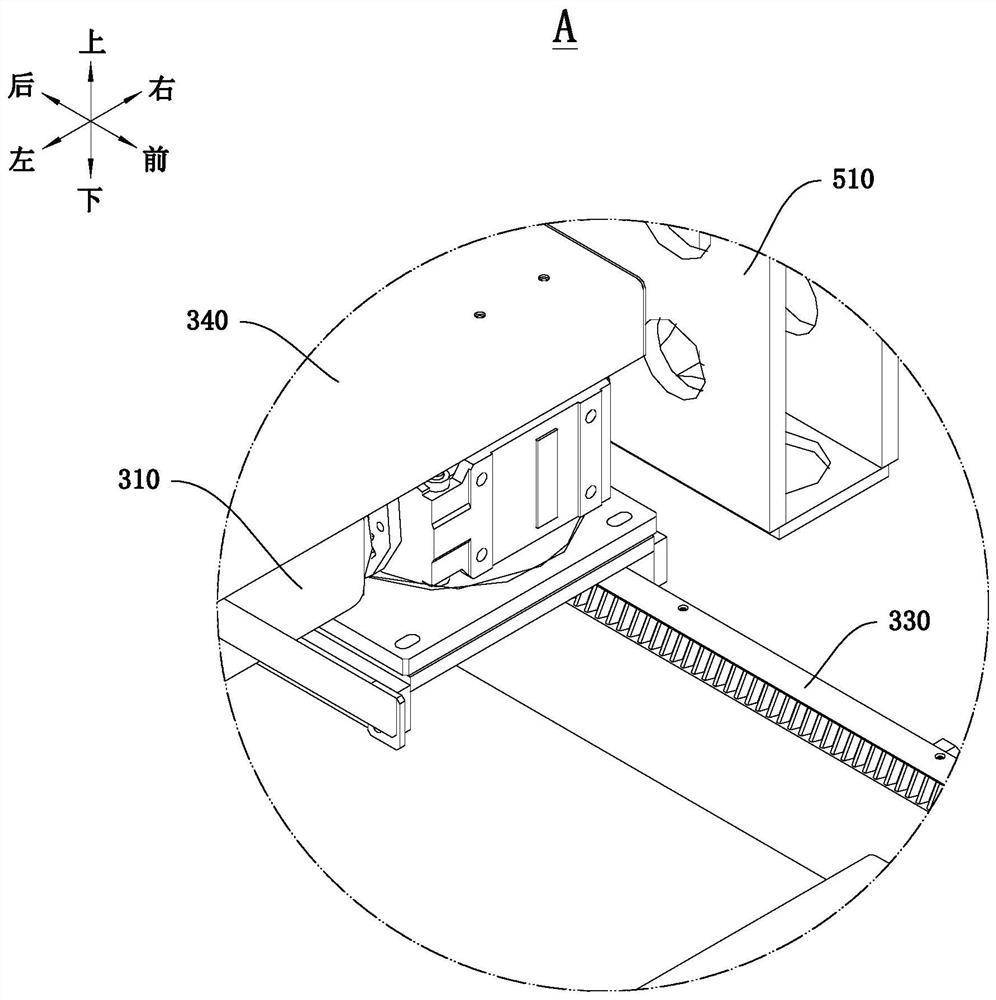
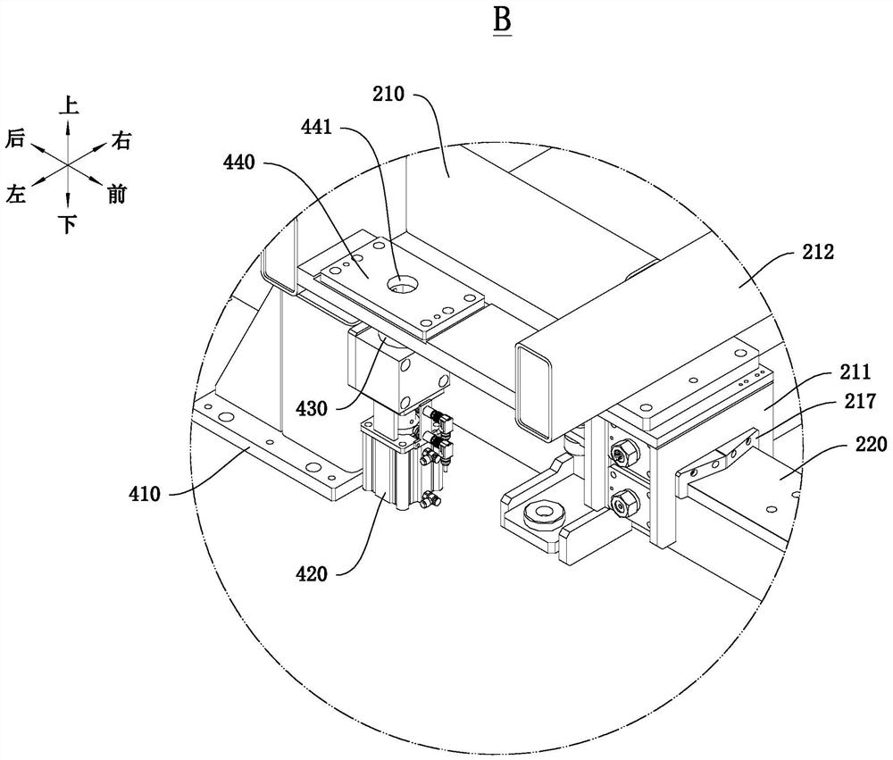
The invention discloses a linear conveying device which comprises a base assembly, a conveying assembly and a driving assembly. The base assembly is provided with at least two base units which are sequentially distributed at intervals in the first direction, and each base unit is provided with a supporting base arranged in the second direction; the conveying assembly is provided with conveying seats and a plurality of conveying rails, the conveying seats are movably mounted on the conveying rails, and the plurality of conveying rails are mounted on the corresponding supporting seats respectively; and the driving assembly is provided with at least two driving parts, and the driving parts are used for driving the conveying seats to move along the conveying rails. The linear conveying device can convey heavy and large-size workpieces, conveying is more stable, meanwhile, the conveying seats are driven by the multiple driving parts, the driving force is larger, high-speed conveying of the heavy and large-size workpieces can be achieved, automatic conveying of the large-size workpieces is achieved, and the production efficiency can be better improved.

Description

technical field [0001] The invention relates to the field of industrial manufacturing, in particular to a linear conveying device. Background technique [0002] In related technologies, conveying systems are usually used in industrial manufacturing to deliver components to designated locations. The conveying system can improve line automation and reduce labor intensity of workers. Therefore, the use of conveying systems has become more and more common. However, at present, for large parts, such as bus bodies, due to the large size of the parts, traditional manual pushing is usually used, resulting in low production efficiency and high labor intensity. Contents of the invention [0003] The present invention aims to solve at least one of the technical problems existing in the prior art. For this reason, the present invention proposes a linear conveying device, which can realize high-speed conveying of large-sized and heavy-weight workpieces. [0004] A linear conveying de...

Claims


Application Information

Patent Timeline
Patent Type & Authority Applications(China)
IPC IPC(8): B65G35/00B65G41/00B65G45/10B65G47/22
CPCB65G35/00B65G41/006B65G45/10B65G47/22
Inventor 柯晓鸿丘邦超杨猛张廷李沛中何庆平
Owner GUANGZHOU MINO AUTOMOTIVE EQUIP CO LTD
Learn More