
Twisting machine

A technology of twisting machine and frame, which is applied in the direction of spinning machine, continuous winding spinning machine, textile and paper making, etc. It can solve the problem of inconvenient replacement process and achieve the effect of improving the replacement speed

Active Publication Date: 2021-10-01
福建省凯利针纺有限公司
View PDF17 Cites 2 Cited by
  • Summary
  • Abstract
  • Description
  • Claims
  • Application Information

AI Technical Summary

Problems solved by technology

[0004] In view of the above-mentioned related technologies, the inventor believes that during the use of the above-mentioned wire-feeding roller, when the yarn on the wire-feeding roller is stripped off, the entire machine needs to be shut down, and the stripped wire-feeding roller is taken out, and then replaced The new wire feed roller continues to be wound. Since the wire feed roller needs to be stopped for replacement, the replacement process is inconvenient

Method used


Image

  • Twisting machine
  • Twisting machine
  • Twisting machine

Examples


Embodiment Construction

[0035] The following is attached Figure 1-8 The application is described in further detail.

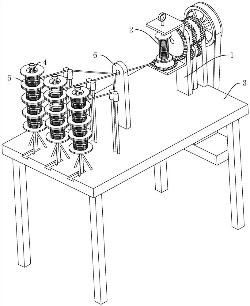
[0036] The embodiment of the application discloses a twisting machine. refer to figure 1 , The twisting machine includes a frame 1, the top of the frame 1 is rotatably connected with a take-up roller 2, one side of the frame 1 is connected with a bottom plate 3 at the same level as the bottom of the frame 1, and the bottom plate 3 is slidably connected with a plug Rod 4, inserting bar 4 extends along the direction perpendicular to base plate 3, inserting bar 4 is provided with three along the width direction of base plate 3, inserting bar 4 is provided with pay-off roller 5, and pay-off roll 5 is provided with a plurality of, machine The frame 1 is provided with a guide plate 6 , and after the yarn on the pay-off roller 5 passes through the guide plate 6 , a plurality of yarns are intertwined with each other, and then wound on the take-up roller 2 .

[0037] refer to figure 2, t...


PUM


Abstract

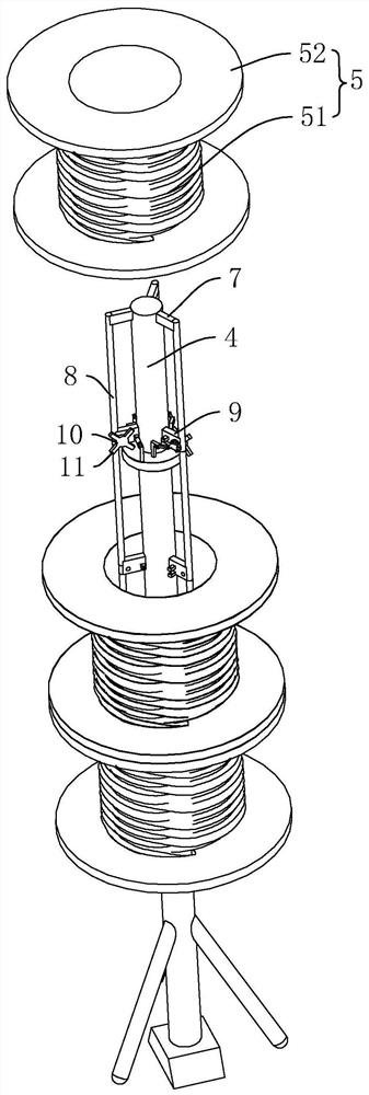
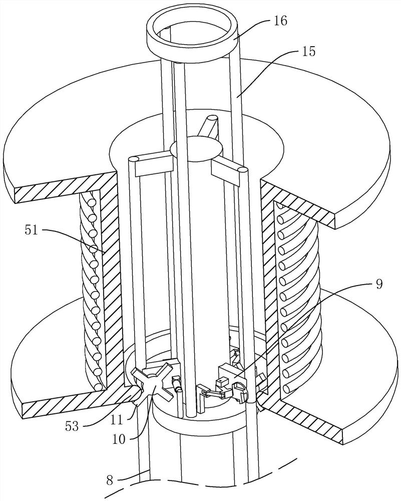
The invention discloses a twisting machine, relates to the technical field of textile equipment, solves the problem that a yarn feeding roller is relatively inconvenient to replace. The twisting machine comprises a rack; a take-up roller is arranged at one end of the rack; a pay-off roller is installed at the end, away from the take-up roller, of the rack; the pay-off roller comprises a middle shaft and limiting plates connected to the two ends of the middle shaft in the length direction; the end, provided with the pay-off roller, of the rack is detachably connected with an insertion rod, and a plurality of transverse rods perpendicular to the axis of the insertion rod are evenly distributed on the side wall of the insertion rod in the circumferential direction; the ends, away from the insertion rod, of the transverse rods are connected with mounting rods parallel to the insertion rod; sleeving parts for middle shaft sleeving are formed between the adjacent mounting rods; the lower ends of the mounting rods are rotationally connected with a limiting seat; two limiting rods perpendicular to each other are arranged on the limiting seat; a limiting ring clamped between the adjacent limiting rods is fixedly arranged on the inner side wall of the lower end of the middle shaft; and a limiting assembly for driving the limiting seat to rotate relative to the mounting rods is arranged on the mounting rods. The replacement speed of the yarn feeding roller can be increased.

Description

technical field [0001] The present application relates to the technical field of textile equipment, in particular to a twisting machine. Background technique [0002] The twisting machine is a textile machinery equipment that twists multiple strands of spun yarn into one strand. Its function is to combine the yarns for linear products or knitting threads. It is widely used in the yarn processing industry and textile machinery industry. [0003] The invention patent with the authorized notification number CN110284232B discloses a twisting machine, which includes a frame and a wire feeding device located on the frame, a tensioning device and a twisting device. Wire frame, the first drive power element that drives the wire take-up frame to rotate along the horizontal center line, the second drive power element that drives the wire take-up roller to rotate along its own axis, the wire block located on the wire take-up frame and the drive wire block along with the wire take-up T...

Claims


Application Information

Patent Timeline
Patent Type & Authority Applications(China)
IPC IPC(8): D01H1/18
CPCD01H1/18
Inventor 郑洪信
Owner 福建省凯利针纺有限公司
Learn More