Chemical production isolation fence and isolation method thereof

A technology for chemical production and isolation fences, which is applied in the direction of fences, building types, buildings, etc., can solve the problems of poor practicability, poor working effect, unsuitable protection for large areas and large spaces, and achieve improved dustproof performance and work good effect

Pending Publication Date: 2021-10-01
庞红娟
View PDF1 Cites 0 Cited by
  • Summary
  • Abstract
  • Description
  • Claims
  • Application Information

AI Technical Summary

Problems solved by technology

[0003] After retrieval, the Chinese Patent Publication No. is CN204627123U, which discloses a fence. The existing fence still has the following defects when used: 1. The device only realizes simple horizontal splicing, and is not suitable for large areas and large spaces. 2. In addition, in the prior art, it is difficult for the guardrails that can realize horizontal and vertical splicing without affecting the universal wheels of the guardrails of the same template. While realizing horizontal and vertical splicing, it can also meet the normal use of the bottom universal wheel, which is poor in practicability; 3. In addition, the splicing process of the guardrail that can realize horizontal and vertical splicing in the prior art is not fast enough Convenient and stable, the actual work effect is not good

Method used


Image

  • Chemical production isolation fence and isolation method thereof
  • Chemical production isolation fence and isolation method thereof
  • Chemical production isolation fence and isolation method thereof

Examples


Embodiment Construction

[0025] The following will clearly and completely describe the technical solutions in the embodiments of the present invention with reference to the accompanying drawings in the embodiments of the present invention. Obviously, the described embodiments are only some, not all, embodiments of the present invention. Based on the embodiments of the present invention, all other embodiments obtained by persons of ordinary skill in the art without making creative efforts belong to the protection scope of the present invention.

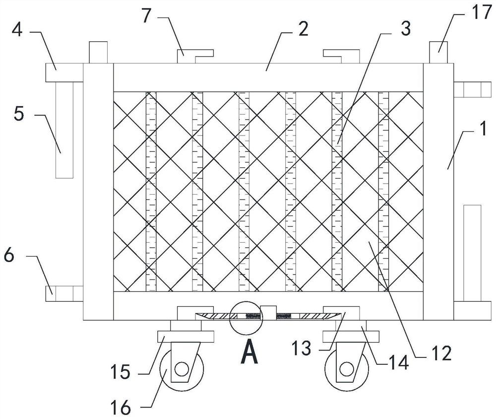
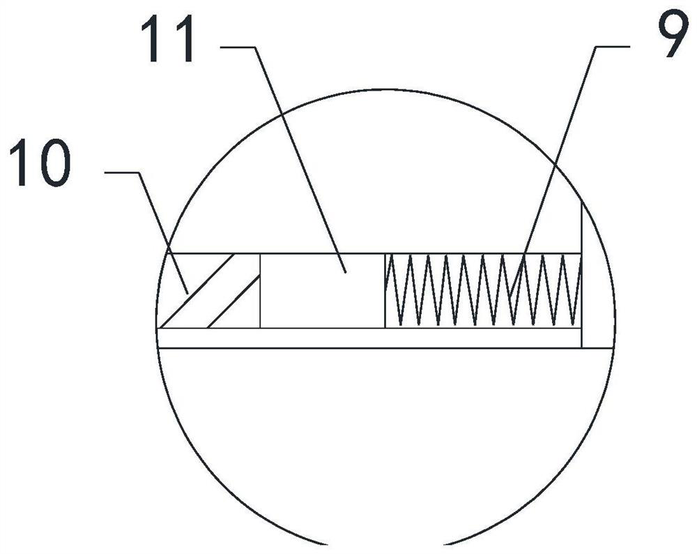
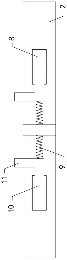
[0026] see Figure 1-4 , a chemical production isolation fence of the present invention, comprising two isolation tubes 1 and two connecting rods 2, the top and bottom ends of the two isolation tubes 1 are respectively connected to the two ends of the two connecting rods 2, and the two isolation tubes 1 and two connecting pipes together form a square frame shape, and a plurality of isolating rods 3 are evenly arranged between the two isolating pipes 1, and the...


PUM


Abstract

The invention relates to the technical field of chemical production, and particularly relates to a chemical production isolation fence and an isolation method thereof. The chemical production isolation fence comprises two isolation pipes and two connecting rods, wherein the top ends and the bottom ends of the two isolation pipes are connected with the two ends of the two connecting rods correspondingly; a plurality of isolation rods are uniformly arranged between the two isolation pipes; connecting plates are arranged at the top of the left side of the isolation pipe located on the left side and the bottom of the right side of the isolation pipe located on the right side correspondingly; fixing rods are arranged at the bottom end of the connecting plate located on the left side and the top end of the connecting plate located on the right side correspondingly; connecting rings are arranged at the bottom end of the left side of the isolation pipe located on the left side and the top end of the right side of the isolation pipe located on the right side correspondingly; two connecting blocks are arranged on the left side and the right side of the connecting rod located at the top correspondingly; and two connecting grooves are formed in the left side and the right side of the connecting rod located at the bottom correspondingly. According to the chemical production isolation fence and the isolation method thereof, the isolation fence can be transversely or longitudinally spliced according to the environment of chemical production, and the isolation fence can meet the protection requirements of chemical production.

Description

technical field [0001] The invention relates to the technical field of chemical production, in particular to a chemical production isolation fence and an isolation method thereof. Background technique [0002] As we all know, the chemical production isolation fence is a kind of fence used in chemical production to isolate and protect chemical production equipment or chemical production sites, to prevent unnecessary personnel from approaching chemical equipment or sites, and to improve the safety of chemical production. It is used in chemical production. has been widely used in the field. [0003] After retrieval, the Chinese Patent Publication No. is CN204627123U, which discloses a barrier. The existing barriers still have the following defects when used: 1. The device only realizes simple horizontal splicing, and is not suitable for large areas and large spaces. 2. In addition, in the prior art, it is difficult for the guardrails that can realize horizontal and vertical sp...

Claims


Application Information

Patent Timeline
Patent Type & Authority Applications(China)
IPC IPC(8): E04H17/14E04H17/22
CPCE04H17/14E04H17/22
Inventor 庞红娟
Owner 庞红娟
Why Eureka
Try Eureka