
A Multi-Branch Gate Valve with Differentiated and Unified Control Structure

A control structure, multi-branch technology, applied in the field of gate valves, can solve the problems of low control efficiency, long time-consuming for multiple groups of valve bodies, inability to unify and differentiate control of multiple groups of branch pipelines, etc.

Active Publication Date: 2021-12-14
法图尔智能装备江苏有限公司
View PDF8 Cites 0 Cited by
  • Summary
  • Abstract
  • Description
  • Claims
  • Application Information

AI Technical Summary

Problems solved by technology

[0005] Based on the above, the traditional gate valve with differentiated and unified control structure is generally a single gate valve structure, and there is no structure that can combine multiple sets of branch pipeline single valve bodies, which cannot save the setting of the main valve of the mainstream pipeline, and cannot be rotated. Unified control of opening and closing of multiple groups of valves in the process of screw jacking, without setting a structure that can realize the classification control of a single valve body after the unified control of four groups of single valve bodies is completely closed, and it is not possible to centrally unify and differentiate multiple groups of branch pipelines Control, due to the interval between the main valve of the main flow pipeline and the auxiliary valve on the branch pipeline, it takes a long time to control multiple sets of valve bodies, and the control efficiency is low
[0006] Therefore, the existing needs are not met, for which we propose a multi-branched gate valve with differentiated and unified control structures

Method used


Image

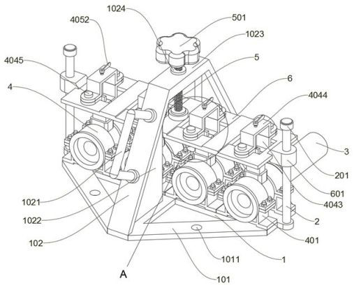
  • A Multi-Branch Gate Valve with Differentiated and Unified Control Structure
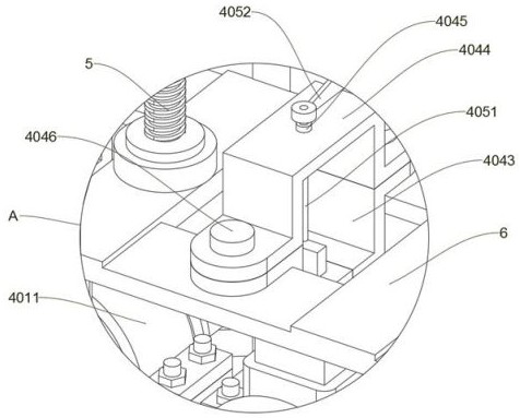
  • A Multi-Branch Gate Valve with Differentiated and Unified Control Structure
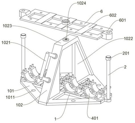
  • A Multi-Branch Gate Valve with Differentiated and Unified Control Structure

Examples


Embodiment Construction

[0077] The following will clearly and completely describe the technical solutions in the embodiments of the present invention with reference to the accompanying drawings in the embodiments of the present invention. Obviously, the described embodiments are only some, not all, embodiments of the present invention.

[0078] In the description of the present invention, unless otherwise stated, the meaning of "plurality" is two or more; the terms "upper", "lower", "left", "right", "inner", "outer" , "front end", "rear end", "head", "tail", etc. indicate the orientation or positional relationship based on the orientation or positional relationship shown in the drawings, and are only for the convenience of describing the present invention and simplifying the description, rather than Nothing indicating or implying that a referenced device or element must have a particular orientation, be constructed, and operate in a particular orientation should therefore not be construed as limiting ...


PUM


Abstract

The invention discloses a multi-branch gate valve with a differentiated and unified control structure, relates to the technical field of gate valves, and solves the problem that existing devices cannot centrally perform unified and differentiated control on multiple groups of branch pipelines. A multi-branch gate valve with differentiated and unified control structures, including a base beam; a single valve body is arranged on the top of the base beam, and the number of single valve bodies is set to four groups; four sets of flange pipes are arranged above the base beam ; A unified control structure is arranged above the base beam; a four-group control structure is arranged below the unified control structure; two sets of limit wedge plates on the opposite inner side of the inclined bracket are used to limit the position, which is convenient for fixing the forward and backward movement position of the translation frame By cooperating with the casing, it is convenient to combine and fix the unified control structure. By combining and installing multiple sets of tributary pipeline single valve bodies, and through the cooperation of the unified control structure and the four-component control structure, it is possible to centrally unify and differentiate multiple sets of tributary pipelines. control.

Description

technical field [0001] The invention relates to the technical field of gate valves, in particular to a multi-branch gate valve with differentiated and unified control structures. Background technique [0002] In the pipeline control process, combined control of the valves in the pipeline is required. Nowadays, the unified and differentiated control of the gate valves in multiple groups of pipeline systems is generally performed by controlling the main valve on the main pipeline and the auxiliary valve on the branch pipeline. The distance between the valve and the auxiliary valve is relatively long, which is not convenient for direct centralized and classified control of multiple groups of branch pipelines. [0003] After retrieval, for example, the patent No. CN109915611A discloses a gate valve with automatic height adjustment function, which includes a main fixed frame installed on the inner wall of the water channel, a main lifting motor fixed on the top of the main fixed ...

Claims


Application Information

Patent Timeline
Patent Type & Authority Patents(China)
IPC IPC(8): F16K11/22F16K11/065F16K3/02F16K27/04F16K31/50F16K31/44
CPCF16K11/22F16K11/0655F16K3/029F16K27/044F16K31/50F16K31/44
Inventor 王佳伟
Owner 法图尔智能装备江苏有限公司
Learn More