Supercharge Your Innovation With Domain-Expert AI Agents!

Visible light and thermal imager image fusion device

A technology of image fusion and thermal imager, which is applied in the field of image fusion, can solve problems such as inability to complement each other, and achieve the effect of simple fusion analysis

Pending Publication Date: 2021-10-01
SHENZHEN TOMORROW SYST INTEGRATION
View PDF0 Cites 0 Cited by
  • Summary
  • Abstract
  • Description
  • Claims
  • Application Information

AI Technical Summary

Problems solved by technology

However, most of the existing imaging devices do not have the fusion of thermal imaging and visible light. The images of visible light and thermal imaging are superimposed in a certain way, resulting in the inability to complement each other and present more image details.

Method used


Image

  • Visible light and thermal imager image fusion device
  • Visible light and thermal imager image fusion device
  • Visible light and thermal imager image fusion device

Examples


Embodiment 1

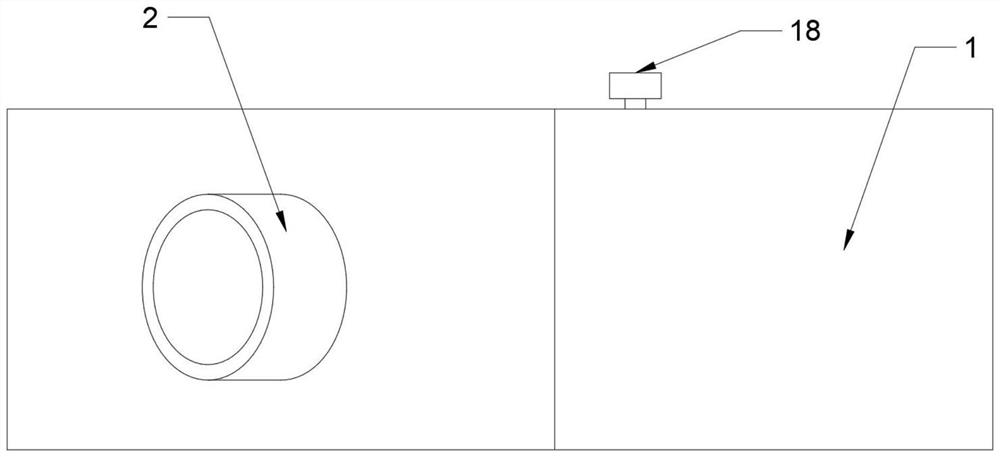
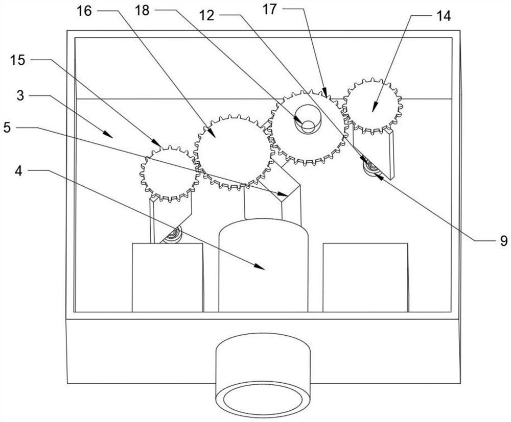
[0021] refer to Figure 1~4 , in an embodiment of the present invention, a visible light and thermal imaging camera image fusion device includes a machine box 1, and the front end of the machine box 1 is provided with a light inlet cylinder 2, and the light beam enters the interior of the device from the light inlet cylinder 2, and the light inlet cylinder 2 The tail end passes through the front end of the machine box 1 and is connected with a light guide tube 4 arranged in the dark room 3 of the machine box 1. The device converges the light beam through the light guide tube 4. The rear end of the prism 5 is provided with a plane mirror A6, the right side of the plane mirror A6 is provided with a plane mirror C8, the left side of the dichroic prism 5 is provided with a plane mirror B7, the front of the plane mirror C8 is provided with a visible light sensor 20, and the front of the plane mirror B7 is provided with a thermal imaging sensor. Sensor 19, the incident light beam af...

Embodiment 2

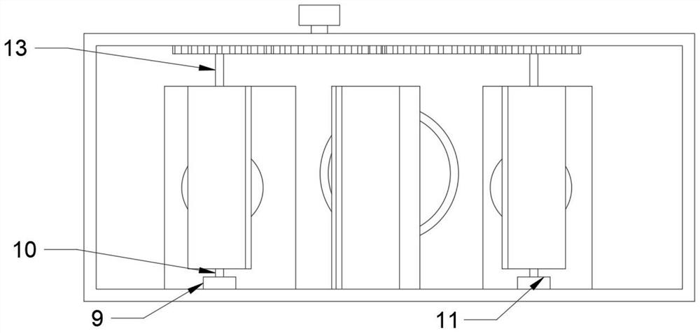
[0024] refer to image 3 , the present invention also provides another embodiment, the difference between this embodiment and the above embodiment is that the bottom ends of the plane mirror B7 and the plane mirror C8 are connected with a connecting rod A10, and the bottom ends of the connecting rod A10 are connected with a bearing 12 , the bearing 12 connected to the bottom end of the plane mirror B7 is connected in the fixed cylinder B11, the bearing 12 connected to the bottom end of the plane mirror C8 is connected in the fixed cylinder A9, and the device adjusts the plane mirror B7 and the plane mirror C8 by setting the positioning cylinder A and the positioning cylinder B The position is limited to prevent the plane mirror B7 and the plane mirror C8 from shifting and affecting the observation results. At the same time, the rotation of the plane mirror B7 and the plane mirror C8 is more stable and smooth through the setting of the bearing 12 .

[0025] The working principl...


PUM


Abstract

The invention relates to the technical field of image fusion, and discloses a visible light and thermal imager image fusion device which comprises a machine box, a light inlet cylinder is arranged at the front end of the machine box, the tail end of the light inlet cylinder penetrates through the front end of the machine box to be connected with a light guide cylinder arranged in a darkroom in the machine box, a beam splitter prism is arranged at the tail end of the light guide cylinder, and a plane mirror A is arranged at the rear end of the beam splitter prism. A plane mirror C is arranged on the right side of the plane mirror A. A plane mirror B is arranged on the left side of the beam splitter prism. A visible light sensor is arranged in front of the plane mirror C. A thermal imaging sensor is arranged in front of the plane mirror B. Incident light is divided into two identical light beams through refraction and reflection of the same light beam, light observation and thermal imaging observation are performed on the two light beams respectively, and visible light observation and thermal imaging observation can be performed on the same light beam at the same time due to the fact that the two light beams have the same characteristics. Therefore, the spectrograms obtained by the two can be simply fused and analyzed.

Description

technical field [0001] The invention relates to the technical field of image fusion, in particular to a visible light and thermal camera image fusion device. Background technique [0002] The movement of matter is the source of infrared rays, thermally imaging the target object, detecting the temperature field of the object, so as to facilitate the user's production operations. Examples include single thermal imaging cameras and thermal imaging cameras. However, most of the existing imaging devices do not have the fusion of thermal imaging and visible light. The images of visible light and thermal imaging are superimposed in a certain way, resulting in the inability to complement each other and present more image details. Therefore, we propose an image fusion method of thermal imaging and visible light to solve the above problems. Contents of the invention [0003] The purpose of the present invention is to provide a visible light and thermal camera image fusion device t...

Claims


Application Information

Patent Timeline
IPC IPC(8): G06T5/50G06T1/00G01J5/00G01J5/02G01J5/08
CPCG06T5/50G06T1/0007G01J5/00G01J5/0205G01J2005/0077G06T2207/20221
Inventor 范伟平
Owner SHENZHEN TOMORROW SYST INTEGRATION
Features
  • R&D
  • Intellectual Property
  • Life Sciences
  • Materials
  • Tech Scout
  • Unparalleled Data Quality
  • Higher Quality Content
  • 60% Fewer Hallucinations
Learn More