Supercharge Your Innovation With Domain-Expert AI Agents!

Workpiece cleaning device

A technology for cleaning devices and workpieces, applied in the direction of cleaning methods using tools, electrical components, cleaning methods and utensils, etc., can solve problems such as long processing time, inability to improve manufacturing efficiency, etc. The effect of shortening the processing time

Active Publication Date: 2022-03-11
FUJIKOSHI MACHINERY
View PDF9 Cites 0 Cited by
  • Summary
  • Abstract
  • Description
  • Claims
  • Application Information

AI Technical Summary

Problems solved by technology

However, the processing time (takt time) of the cleaning and dewatering process is long, and it is at the bottleneck stage, which is a major factor that cannot improve the manufacturing efficiency.

Method used


Image

  • Workpiece cleaning device
  • Workpiece cleaning device
  • Workpiece cleaning device

Examples


Embodiment Construction

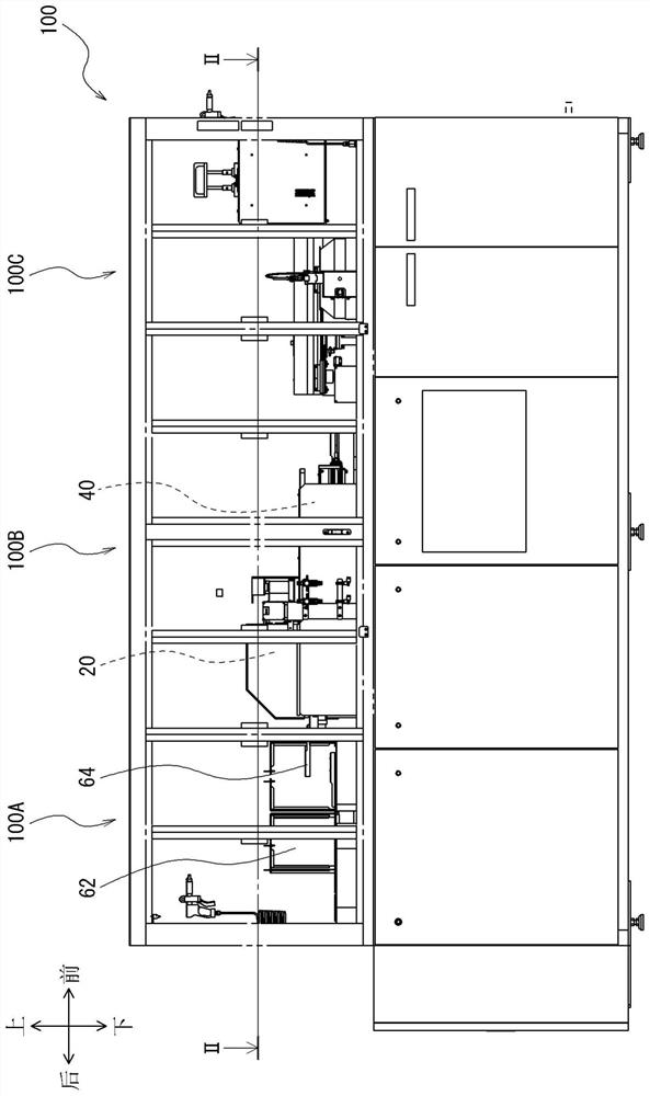
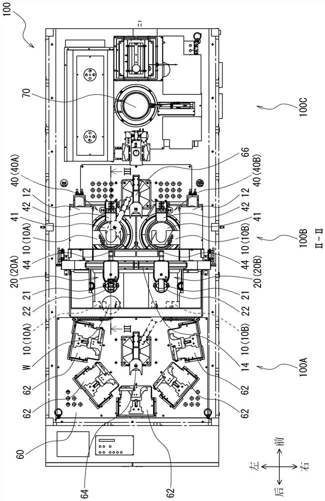
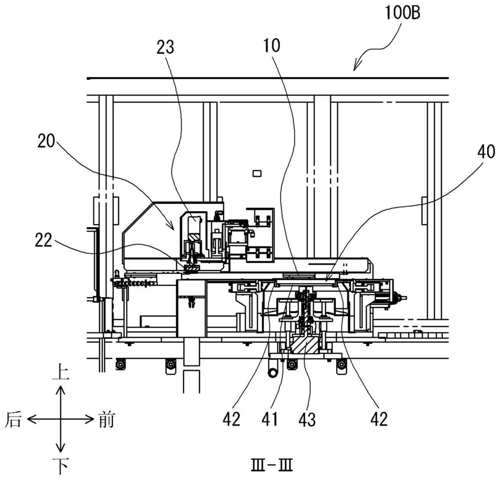
[0016] Hereinafter, embodiments of the present invention will be described in detail with reference to the drawings. figure 1 It is a schematic diagram (side view) showing an example of the workpiece cleaning device 100 according to the embodiment of the present invention. in addition, figure 2 yes figure 1 The II-II line sectional view in, image 3 yes figure 2 Sectional view of line III-III in. In addition, for convenience of explanation, the directions of front and rear, left and right, and up and down in the workpiece cleaning device 100 may be described by arrows in the drawings. In addition, in all the drawings for explaining the respective embodiments, members having the same functions are denoted by the same reference numerals, and overlapping description thereof may be omitted.

[0017] The workpiece cleaning device 100 of the present embodiment is a device for cleaning a flat workpiece W. As shown in FIG. As this workpiece W, a disk-shaped wafer (silicon wafe...


PUM


Abstract

To provide a workpiece cleaning device capable of shortening the processing time in the process of cleaning and dewatering a flat workpiece such as a wafer, and improving manufacturing efficiency. The workpiece cleaning device (100) of the present invention includes: a loading portion (60), a plurality of magazines (62) containing workpieces (W) are placed on the loading portion in an arc shape; the first hand portion (64) , which is arranged at the center of a plurality of magazines (62), and the workpieces (W) are sequentially taken out from the plurality of magazines (62) and alternately placed on the first arm (10A) and the second arm (10B) and cleaning mechanism (20), cleaning mechanism (20) has sprinkling part (21) and contact cleaning part (22), and contact cleaning part (22) is constituted, under the state of being driven by rotation or amplitude, in relative to The conveyance direction of the workpiece (W) reciprocates in a direction intersecting at 90 degrees or a predetermined angle, and conveyance and cleaning of the workpiece (W) are performed in parallel.

Description

technical field [0001] The invention relates to a workpiece cleaning device for cleaning flat workpieces. Background technique [0002] As one of the steps of manufacturing a semiconductor device or the like, there is a step of polishing a wafer (silicon wafer or the like). As an example, a method is known in which a wafer is bonded to a fixed plate while being pressed against a stage while rotating it, thereby polishing the wafer. [0003] In the case of polishing the wafer by the above-mentioned method, if dust adheres to the surface of the wafer bonded to the fixed plate, this part will be strongly pressed against the platform and ground much more than the surrounding area, so it may A problem occurs that predetermined flatness cannot be obtained. Therefore, it is important to clean the wafer to remove dust before polishing. As an example of an apparatus for cleaning a wafer, there is disclosed a cleaning apparatus described in Patent Document 1 (see Japanese Patent Ap...

Claims


Application Information

Patent Timeline
Patent Type & Authority Patents(China)
IPC IPC(8): H01L21/67B08B1/00B08B1/02B08B3/02
CPCH01L21/67046B08B3/022B08B1/02B08B1/002
Inventor 小布施敦史杉浦敬二
Owner FUJIKOSHI MACHINERY
Features
  • R&D
  • Intellectual Property
  • Life Sciences
  • Materials
  • Tech Scout
  • Unparalleled Data Quality
  • Higher Quality Content
  • 60% Fewer Hallucinations
Learn More