Automatic pushing mechanism of trepanning cutter
A technology of pushing mechanism and nesting knife, which is applied in the direction of drilling/drilling equipment, drilling tool accessories, transportation and packaging, etc. It can solve the scrapping of parts and nesting knives, processing interference, and easy retention of residual materials in the nesting The internal problems of the knife can be solved to achieve the effect of reducing unreasonable loss, improving production efficiency and reducing auxiliary operation time
- Summary
- Abstract
- Description
- Claims
- Application Information
AI Technical Summary
Problems solved by technology
Method used
Image

Examples
Embodiment 1
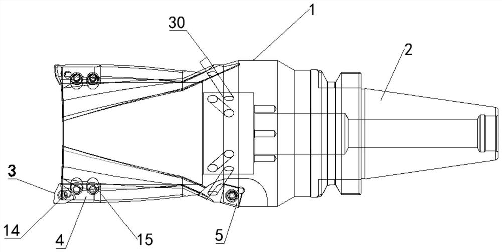
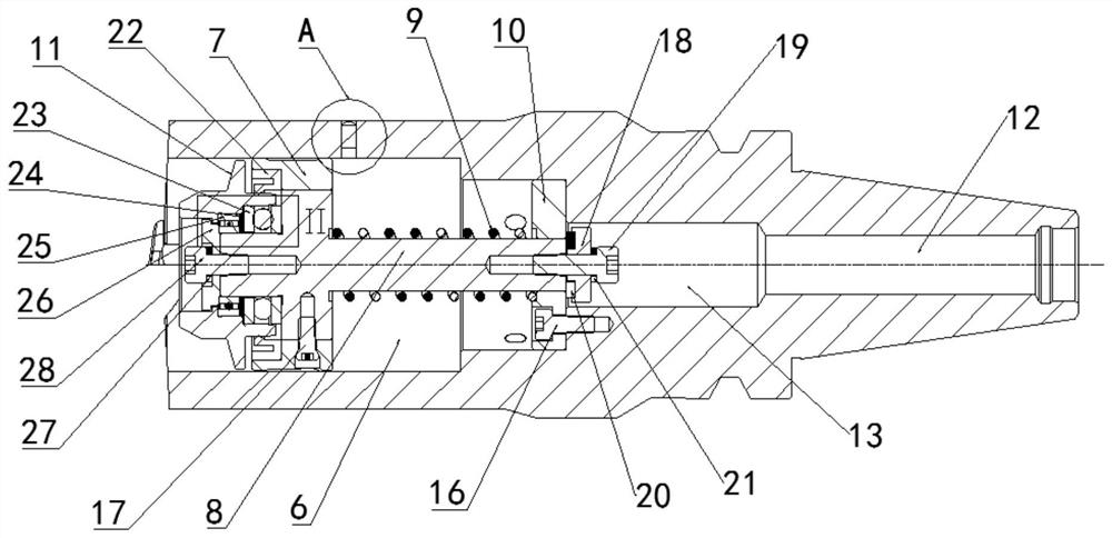
[0030] like Figure 1-7 As shown, the automatic pushing mechanism of the nesting knife according to the embodiment of the present invention includes a knife body 1 and a knife handle 2, the knife body 1 is located at one end of the knife handle 2, and the knife body 1 is far away from the knife handle 2 The side of one end is provided with several nesting blades 3, and the nesting blades 3 are fixedly connected with the cutter body 1 through the cutter block 4, and several chamfering blades 5 are arranged at the middle position of the side of the cutter body 1, One end of the knife body 1 away from the knife handle 2 is provided with a through groove 6, the inside of the through groove 6 is provided with a sliding sleeve 7, and the middle position of one end of the sliding sleeve 7 is provided with a 7 and a sliding shaft 8 located inside the through groove 6, the sliding shaft 8 is sleeved with a spring 9, and one end inside the through groove 6 is provided with a The bushin...
Embodiment 2
[0033] like Figure 1-7 As shown, the cutter body 1 is located at one end of the handle 2, and the side of the cutter body 1 away from the end of the handle 2 is provided with several nesting blades 3, and the nesting blades 3 pass through the knife block 4 It is fixedly connected with the cutter body 1, a number of chamfering blades 5 are arranged at the middle position of the side of the cutter body 1, and a through groove 6 is opened inside the cutter body 1 far away from the end of the knife handle 2, and the through groove 6 is arranged at the end of the cutter body 1. The inside of the groove 6 is provided with a sliding sleeve 7, and the middle position of one end of the sliding sleeve 7 is provided with a sliding shaft 8 inserted through the sliding sleeve 7 and located inside the through groove 6, and the sliding shaft 8 is sleeved with a A spring 9, a bushing 10 matching the sliding shaft 8 and the spring 9 is provided at one end of the through groove 6, and a pushin...
Embodiment 3
[0035] like Figure 1-7As shown, the cutter body 1 is located at one end of the handle 2, and the side of the cutter body 1 away from the end of the handle 2 is provided with several nesting blades 3, and the nesting blades 3 pass through the knife block 4 It is fixedly connected with the cutter body 1, a number of chamfering blades 5 are arranged at the middle position of the side of the cutter body 1, and a through groove 6 is opened inside the cutter body 1 far away from the end of the knife handle 2, and the through groove 6 is arranged at the end of the cutter body 1. The inside of the groove 6 is provided with a sliding sleeve 7, and the middle position of one end of the sliding sleeve 7 is provided with a sliding shaft 8 inserted through the sliding sleeve 7 and located inside the through groove 6, and the sliding shaft 8 is sleeved with a A spring 9, a bushing 10 matching the sliding shaft 8 and the spring 9 is provided at one end of the through groove 6, and a pushing...
PUM
 Abstract
Description
Claims
Application Information
 - R&D
- Intellectual Property
- Life Sciences
- Materials
- Tech Scout
- Unparalleled Data Quality
- Higher Quality Content
- 60% Fewer Hallucinations
Browse by: Latest US Patents, China's latest patents, Technical Efficacy Thesaurus, Application Domain, Technology Topic, Popular Technical Reports.
© 2025 PatSnap. All rights reserved.Legal|Privacy policy|Modern Slavery Act Transparency Statement|Sitemap|About US| Contact US: help@patsnap.com