
Object-carrying chair back for automobile seat

A technology for car seats and seat backs, which is applied to vehicle seats, special positions of vehicles, vehicle components, etc., can solve problems such as poor structural stability and complicated mechanisms for controlling overturning, and achieve increased stability, rich functionality, The effect of increasing daily functionality

Inactive Publication Date: 2021-10-08
GUANGZHOU HONGYI ZHICHE TECH CO LTD
View PDF8 Cites 0 Cited by
  • Summary
  • Abstract
  • Description
  • Claims
  • Application Information

AI Technical Summary

Problems solved by technology

[0003] The primary purpose of the present invention is to address the above-mentioned defects and deficiencies, to solve the technical problems of the over-complex control mechanism and poor structural stability in the prior art, and to provide a car seat loadable object with simple structure and smooth and stable control. chair back

Method used


Image

  • Object-carrying chair back for automobile seat
  • Object-carrying chair back for automobile seat
  • Object-carrying chair back for automobile seat

Examples


Embodiment 1

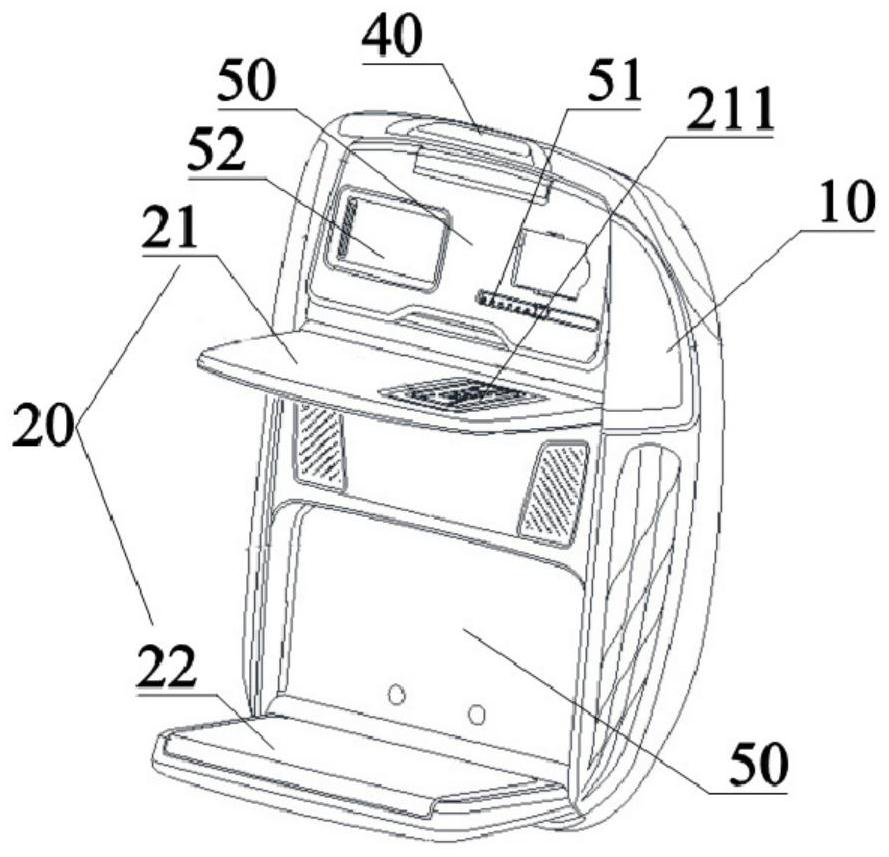
[0043] Embodiment 1 of the present invention provides an electric multifunctional rear seat back of a car seat, which includes: a shell provided on the back main body 10 , an object-carrying mechanism and a foot dragging mechanism.

[0044] A first accommodating groove 50 and a second accommodating groove 50 are defined on the housing. The shell defines a pen slot 51 at the bottom of the first accommodating slot. A C-shaped soft clamp 511 is provided in the middle area of ​​the pen holder, and a plurality of anti-skid blocks 512 are evenly arranged on the groove bottom of the pen holder. The top of the housing is provided with a PCB control board 40 . The housing is provided with a mirror at the bottom of the first accommodating tank. In this embodiment, the mirror includes a frame 521 , a mirror 522 and a cover 523 . The mirror surface 522 is connected to the casing through the mirror frame 521 , and the cover plate 523 is covered on the mirror surface 522 and is slidably ...

Embodiment 2

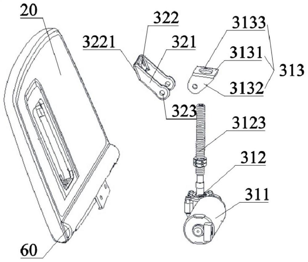
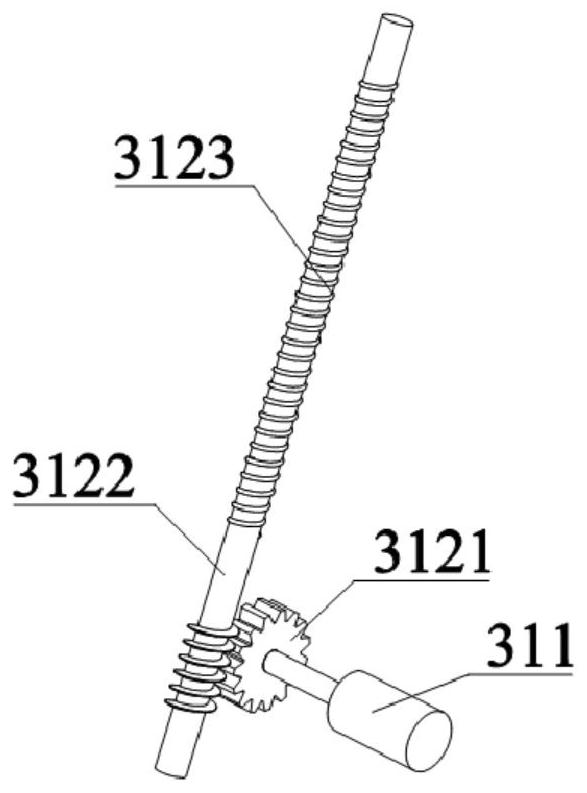
[0052] Embodiment 2 provides another lifting unit 31 structure, including a toothed plate 33 rotatably connected to the swing connector 32 , and a transmission gear 34 meshed with the toothed plate 33 . Simultaneously, the tooth plate 33 can be installed inside the seat back 10 through installation structures such as chute and slide rail, but not limited to these installation structures of chute and slide rail, and any structure that can make the tooth plate 33 be installed is all possible. The transmission gear 34 is connected with the motor 311 and drives the gear plate 33 meshed with it to move up and down under the action of rotation, and the up and down motion of the gear plate 33 drives the swing connector 32 hinged to it to swing and stretch, thereby realizing the flipping of the loading plate 20 .


PUM


Abstract

The invention discloses an object-carrying chair back for an automobile seat. The object-carrying chair back comprises a back main body, at least one object carrying plate rotationally connected with the back main body, and an overturning control mechanism; the overturning control mechanism comprises a lifting unit and a swinging connecting piece which is rotationally connected with the lifting unit and is in sliding connection with the loading plate; during use, the lifting unit ascends and descends to enable the swing connecting piece to slide along the back main body, and therefore the object carrying plate is driven to turn over to the back main body. The lifting unit ascends and descends to enable the swing connecting piece to extend towards the outer side of the back main body, so that the object carrying plate is driven to overturn to the back main body, and overturning movement of the object carrying plate is achieved. Compared with the prior art, the control structure is simple and stable, a triangular structure is formed by the connecting position of the object carrying plate and the back main body, the connecting position of the swing connecting piece and the lifting unit and the connecting position of the swing connecting piece and the object carrying plate, and the stability of the structure and control is improved.

Description

technical field [0001] The invention relates to the technical field of car seats, and more particularly, relates to a loadable seat back for a car seat. Background technique [0002] Usually, when people design car seats, they focus on taking comfort, cleanliness, and adjustment functionality into consideration. In this regard, many existing technologies have made technical improvements one after another. However, little thought has been given to the functionality of the back of a car seat facing the rear passenger. In order to satisfy the requirement that passengers in the rear seat can place some items in the car, such as notebooks, pens, mobile electronic devices, etc., the Chinese invention patent CN 210174695U is a multifunctional rear table board, and a reversible table board and footrest are arranged on the back of the seat , to facilitate the use of passengers. The mechanism for controlling the overturning of the table board and the footrest is mainly realized by a...

Claims


Application Information

Patent Timeline
Patent Type & Authority Applications(China)
IPC IPC(8): B60N3/00B60N2/90B60R7/04
CPCB60N3/001B60N3/004B60N2/995B60R7/04
Inventor 卢叔仁
Owner GUANGZHOU HONGYI ZHICHE TECH CO LTD
Features
  • Generate Ideas
  • Intellectual Property
  • Life Sciences
  • Materials
  • Tech Scout
  • Unparalleled Data Quality
  • Higher Quality Content
  • 60% Fewer Hallucinations
Learn More