A kind of rigid coupling that can be used for high-speed rotary connection and its preparation method

A rigid coupling, high-speed rotation technology, used in rigid shaft couplings, couplings with safety disconnect joints, couplings, etc., can solve the problem of large installation space, small torque transmission, shaft, bearing, etc. and other problems such as failure of moving parts, to achieve the effect of reducing concentricity requirements, protecting from damage, and increasing reliability

Active Publication Date: 2022-05-20
JIUJIANG HANTANG OPTOELECTRONICS TRANSMISSION TECH CO LTD
View PDF0 Cites 0 Cited by
  • Summary
  • Abstract
  • Description
  • Claims
  • Application Information

AI Technical Summary

Problems solved by technology

[0002] Coupling is a general-purpose component in the field of mechanical transmission. It is mainly used for the connection between the driving shaft and the driven shaft. At present, the coupling is divided into two categories: rigid and flexible. Due to the low sensitivity of the flexible coupling, small torque transmission, The installation space is large, so rigid couplings are increasingly used in some high-precision and high-torque motion situations. The ultra-low inertia and high sensitivity characteristics of rigid couplings can play an excellent role in servo motion systems. performance, but the existing rigid couplings have high requirements on the symmetry accuracy of the axis, especially in the environment of high-speed movement, the small relative displacement between the shafts is easy to damage the coupling, and then make the shaft, bearing and other moving parts Therefore, how to realize a safe and reliable rigid coupling in the high-speed and high-torque motion mode is a technical problem in the field of mechanical transmission at present.

Method used


Image

  • A kind of rigid coupling that can be used for high-speed rotary connection and its preparation method
  • A kind of rigid coupling that can be used for high-speed rotary connection and its preparation method
  • A kind of rigid coupling that can be used for high-speed rotary connection and its preparation method

Examples


Embodiment

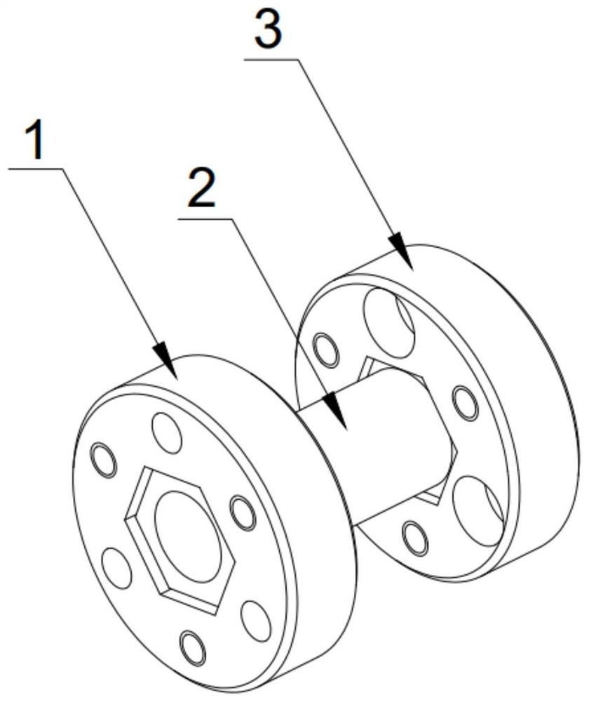
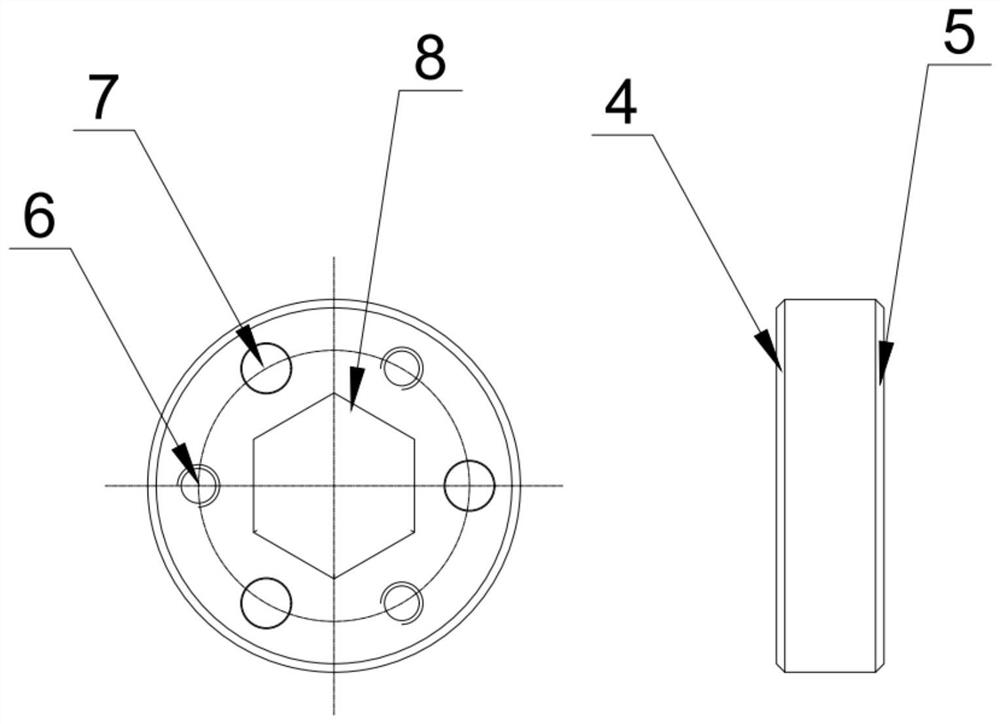
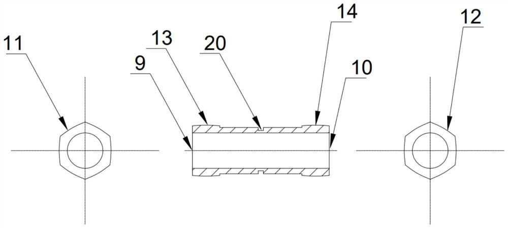
[0025] Example: see attached Figure 1-4 , the present invention provides a technical solution: a rigid coupling that can be used for high-speed rotary connection, which includes a left connecting flange 1, a connecting shaft 2 and a right connecting flange 3, and the center of the end surface of the left connecting flange 1 runs through A regular hexagonal inner hole 8 is provided, and on the end face of the left connecting flange 1, there are a plurality of threaded holes 6 and counterbore 1 7 in a circular array centered on the regular hexagonal inner hole 1 , and the left connecting flange 1 passes through The regular hexagonal inner hole-8 is fitted on the left end b13 of the connecting shaft 2; specifically, the left connecting flange 1 is fixed on the user's driving shaft through the counterbore-7 (or threaded hole-6) thereon .

[0026] The center position of the end face of the right connecting flange 3 is provided with a regular hexagonal inner hole 19, and the end f...


PUM


Abstract

The invention discloses a rigid shaft coupling which can be used for high-speed rotary connection and a preparation method thereof, which comprises a left connecting flange, a connecting shaft and a right connecting flange, and a positive six Hexagonal inner hole 1, on the end face of the left connecting flange and with the regular hexagonal inner hole 1 as the center, there are a plurality of threaded holes 1 and counterbores 1, and the left connecting flange passes through the regular hexagonal inner hole 1. The polygonal inner hole is fitted on the left end b of the connecting shaft. In order to protect the important parts of the transmission system from being damaged, the device of the present invention can make the connecting shaft play the role of a fuse by opening an annular notch at the radial position of the connecting shaft. When the relative torque between the driving shaft and the driven shaft exceeds the designed When the maximum value is reached, the connecting shaft will break, so as to protect the important transmission parts on the driving shaft and the driven shaft from damage, and replace the connecting shaft after troubleshooting.

Description

technical field [0001] The invention specifically relates to the technical field of shaft couplings, in particular to a rigid shaft coupling that can be used for high-speed rotary connections and a preparation method thereof. Background technique [0002] Coupling is a general-purpose component in the field of mechanical transmission. It is mainly used for the connection between the driving shaft and the driven shaft. At present, the coupling is divided into two categories: rigid and flexible. Due to the low sensitivity of the flexible coupling, small torque transmission, The installation space is large, so rigid couplings are increasingly used in some high-precision and high-torque motion situations. The ultra-low inertia and high sensitivity characteristics of rigid couplings can play an excellent role in servo motion systems. performance, but the existing rigid couplings have high requirements on the symmetry accuracy of the axis, especially in the environment of high-spe...

Claims


Application Information

Patent Timeline
Patent Type & Authority Patents(China)
IPC IPC(8): F16D1/033F16D9/08B23P15/14
CPCF16D1/033F16D9/08B23P15/14
Inventor 李问国张方方付宏宝
Owner JIUJIANG HANTANG OPTOELECTRONICS TRANSMISSION TECH CO LTD
Why Eureka
Try Eureka