

Tail gas post-treatment seal
A technology for after-treatment of exhaust gas and installation of covers, which is applied in the direction of exhaust gas treatment, exhaust devices, noise reduction devices, etc., which can solve the problems of cost increase, achieve the effect of reducing coaxiality requirements and improving the convenience of assembly
- Summary
- Abstract
- Description
- Claims
- Application Information
AI Technical Summary
Problems solved by technology
Method used
Image

Examples
Embodiment Construction
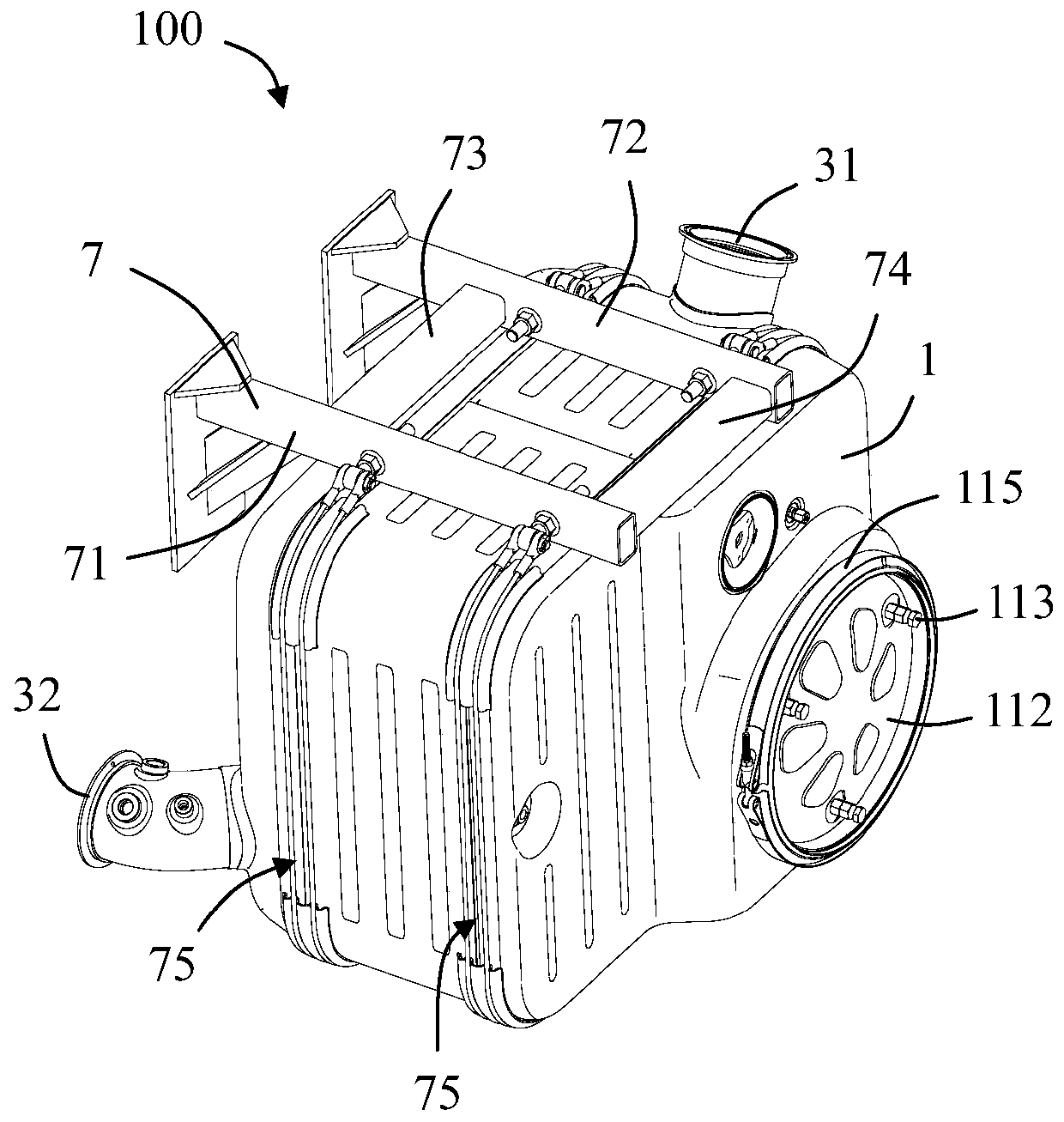
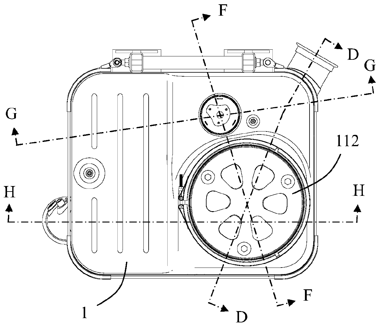
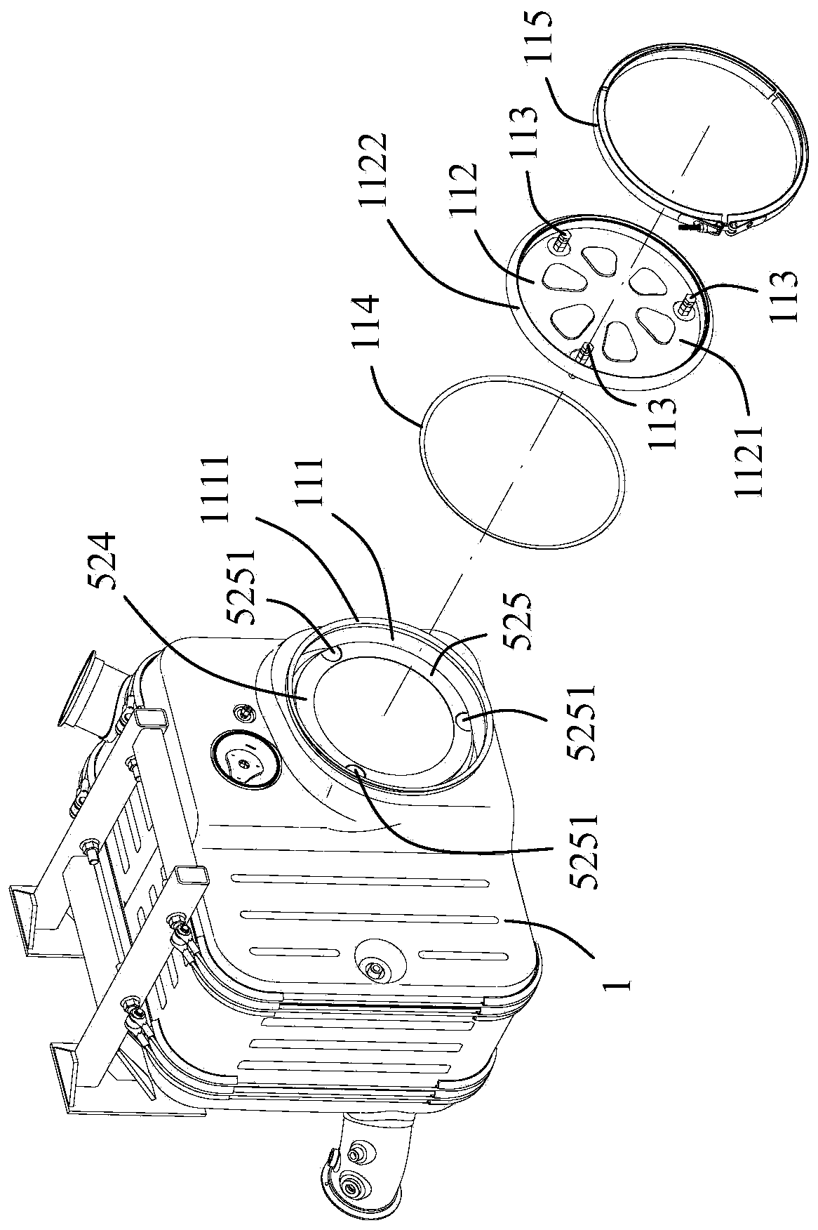
[0033] Specific implementations of the present invention will be described in detail below with reference to the accompanying drawings, wherein if there are several specific implementations, the features in these implementations can be combined with each other if there is no conflict. When the description refers to the drawings, unless otherwise stated, the same numerals or symbols in different drawings indicate the same or similar elements. What is described in the following exemplary detailed description does not represent all implementations of the invention, but rather they are merely examples of products consistent with the invention as recited in the claims of the invention.
[0034] The terminology used in the present invention is only for the purpose of describing specific embodiments, and is not intended to limit the protection scope of the present invention. It should be understood that words such as "first", "second" and similar words used in the description and cla...
PUM
 Abstract
Description
Claims
Application Information