Permanent-magnet coupling mechanism between shafts

A permanent magnet coupling, shaft-to-shaft technology, applied in electromechanical devices, electromechanical transmission devices, electrical components, etc., can solve the problems of difficulty in accurately ensuring the alignment of two shafts, magnetic field distribution, complex structure and operation, etc., to reduce adjustment. The effect of reducing displacement and concentricity requirements and wide application range

Inactive Publication Date: 2013-09-18
JIANGSU MAGNET VALLEY TECH
View PDF5 Cites 5 Cited by
  • Summary
  • Abstract
  • Description
  • Claims
  • Application Information

AI Technical Summary

Problems solved by technology

Due to the complex and changeable operation of the system, it is difficult to accurately ensure the alignment of the two axes, and the equipment will vibrate after a period of operation, thereby accelerating wear and shortening the life of the equipment
[0004] 2. At present, frequency conversion and speed regulation are widely used in industrial sites. The output speed is controlled by controlling the motor. The price is relatively expensive, and the structure and operation are complicated. The power electronic devices of the frequency converter work in the switch state, thus generating a large number of harmonics and polluting the power grid. Affects communication, and the stability of electronic devices is not good, it is easy to age, the service life is not long, and the requirements for the environment are high, and there are great requirements for the ambient temperature, humidity and dust, so it is not suitable for working in harsh environments
In this type of coupler with existing structures, the direction of the magnetic field in the permanent magnets distributed along the circumference is usually perpendicular to the magnetic field action surface between the conductor rotor and the permanent magnet rotor, and the magnetic field distribution is scattered and the intensity is not high (the highest magnetic induction The strength can only reach 400~500mT), if you want to transmit a large torque, you need to make the structure larger, which limits the promotion of this technology

Method used


Image

  • Permanent-magnet coupling mechanism between shafts
  • Permanent-magnet coupling mechanism between shafts
  • Permanent-magnet coupling mechanism between shafts

Examples


Embodiment Construction

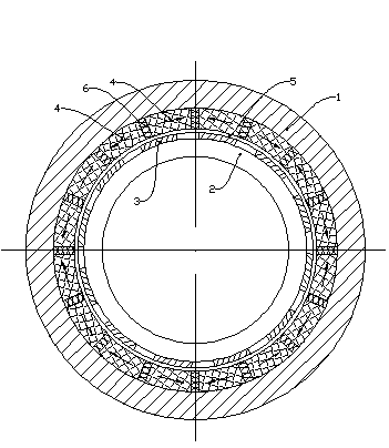
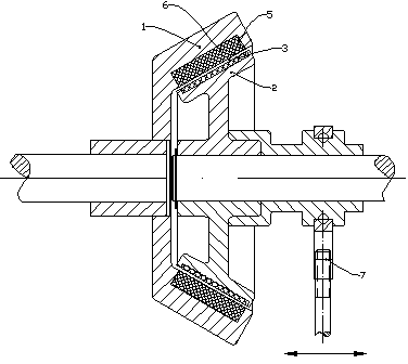
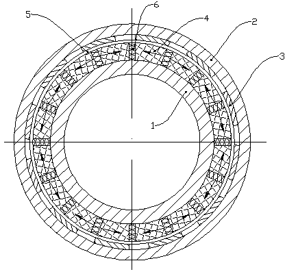
[0017] As shown in the figure, the inter-shaft permanent magnet coupling mechanism of the present invention includes a permanent magnet rotor 1 and a conductor rotor 2 arranged coaxially. Permanent magnets 4 and conductors 3 are distributed on the permanent magnet rotor 1 and conductor rotor 2 respectively. There is a conical air gap 5 between the rotor 1 and the conductor rotor 2; a plurality of permanent magnets 4 are distributed along the circumference, and a magnetizer 6 made of a magnetically permeable material is arranged between adjacent permanent magnets 4; the permanent magnets The magnetic pole direction of 4 (that is, the direction of the connecting line between the S pole and the N pole) is located in the circumferential direction of the permanent magnet rotor 1, and the magnetic pole directions of adjacent permanent magnets 4 (indicated by the arrow direction in the figure) face or face each other.

[0018] The mechanism also includes an adjusting device 7 capable ...


PUM


Abstract

The invention relates to a mechanism transmission device, in particular to a permanent-magnet coupling mechanism between shafts. The permanent-magnet coupling mechanism is used for transmitting torque between two rotation shafts and comprises a permanent-magnet rotor and a conductor rotor which are arranged coaxially. Permanent-magnets and conductors are respectively distributed on the permanent-magnet rotor and the conductor rotor, and a conical air gap is formed between the permanent-magnet rotor and the conductor rotor. The permanent-magnets on the permanent-magnet rotor are distributed circumferentially, and magnetizers made of magnetic materials are mounted between the adjacent permanent-magnets. Directions of magnetic poles of the permanent-magnets extend along the circumference of the permanent-magnet rotor, and directions of the magnetic poles of the adjacent permanent-magnets are opposite or reversed. The permanent-magnet coupling mechanism is capable of transmitting high torque adjustably, and is compact in structure, convenient to mount and stable and reliable in transmission and adjustment.

Description

technical field [0001] The invention relates to a mechanism transmission device, in particular to an inter-shaft permanent magnetic coupling mechanism for torque transmission between two rotating shafts. Background technique [0002] For torque output and adjustment, there are many ways in the prior art, including: [0003] 1. Coupling mechanisms widely used in industry at present, these mechanisms are mostly rigid or hydraulic coupling connections, and the transmission torque and speed cannot be adjusted. Due to the complex and changeable operating conditions of the system, it is difficult to accurately ensure the alignment of the two axes. After a period of operation, the equipment will vibrate, which will accelerate wear and shorten the life of the equipment. [0004] 2. At present, frequency conversion and speed regulation are widely used in industrial sites. The output speed is controlled by controlling the motor. The price is relatively expensive, and the structure an...

Claims


Application Information

Patent Timeline
Patent Type & Authority Applications(China)
IPC IPC(8): H02K51/00
Inventor 徐俊峰
Owner JIANGSU MAGNET VALLEY TECH
Why Eureka
Try Eureka