Disinfection device for infectious ward
A technology of a disinfection device and an infectious disease room, applied in the field of medical equipment, can solve problems such as poor disinfection effect, and achieve the effect of increasing the disinfection range
- Summary
- Abstract
- Description
- Claims
- Application Information
AI Technical Summary
Problems solved by technology
Method used
Image

Examples
Embodiment 1
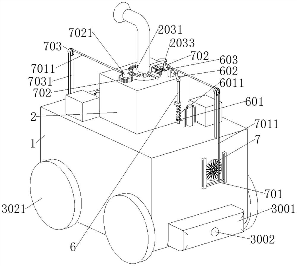
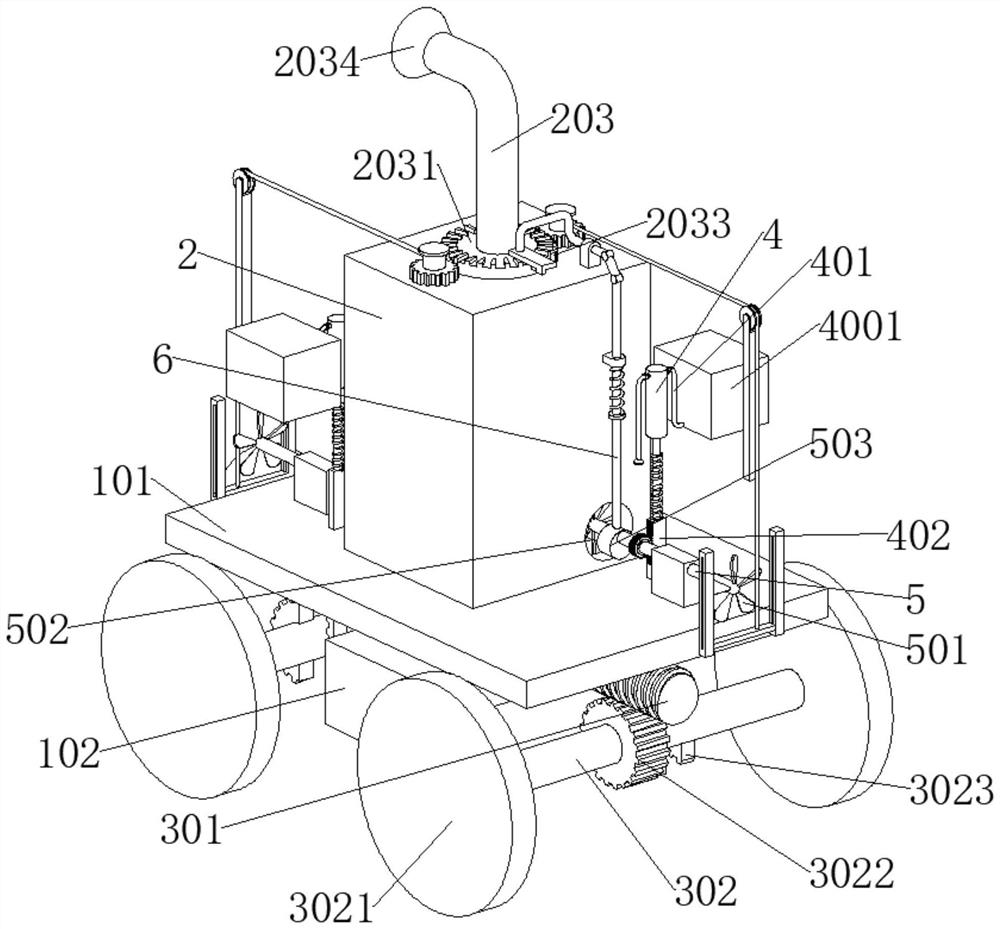
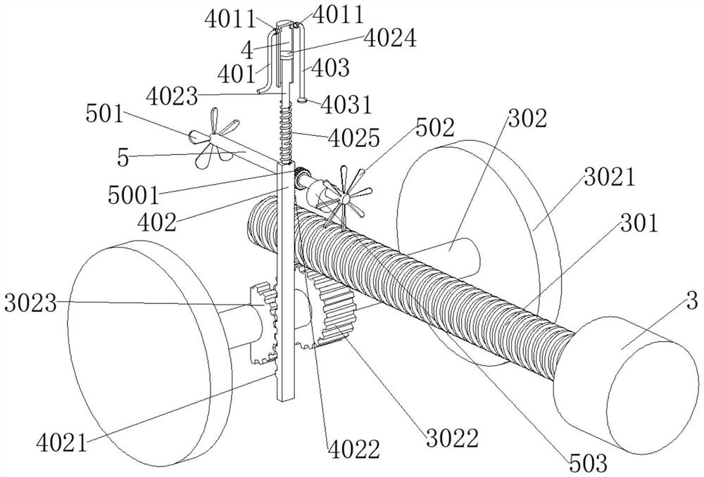
[0028] refer to figure 1 , figure 2 and Figure 6 The present invention provides a technical solution: a disinfection device for an infectious disease room, including an installation box 1, a semiconductor heat sink 202, a motor 3, and a battery 102 for powering the motor 3 and the semiconductor heat sink 202, and a partition is fixedly connected in the installation box 1. The plate 101, the partition 101 is fixedly connected with the disinfection box 2, the disinfection box 2 is fixedly connected with the installation box 1, the semiconductor heat sink 202 is fixedly connected with the disinfection box 2, and the installation box 1 is fixedly connected with the anti-collision block 3001. The collision block 3001 is provided with a pressure-sensitive switch 3002 for controlling the positive and negative rotation of the motor 3, the motor 3 is fixedly connected to the anti-collision block 3001, the output end of the motor 3 is fixedly connected with a worm 301, and the inside...
Embodiment 2
[0037] refer to figure 1 and Figure 4 , basically the same as Embodiment 1, furthermore, the disc 2031 is provided with a cleaning mechanism for cleaning the circular filter screen 7, the cleaning mechanism includes a scraper 701, and the scraper 701 is slidably connected to the installation box 1, and the scraper 701 fits with the circular filter screen 7, the full-toothed gear 702 is connected with rotation on the disinfection box 2, the side wall of the disc 2031 is provided with incomplete teeth 2033, the incomplete teeth 2033 on the full-toothed gear 702 and the disc 2031 Teeth 2033 mesh intermittently, full-toothed gear 702 is fixedly connected with storage roller 7021, and storage roller 7021 is fixedly connected with drawstring 7011, and the end of drawstring 7011 away from storage roller 7021 is fixedly connected with scraper 701, fixed on installation box 1 A pole 7031 is connected, and the top of the pole 7031 is rotatably connected with a guide wheel 703 for guid...
Embodiment 3
[0040] refer to Figure 7 , basically the same as Embodiment 1, furthermore, the disc 2031 is provided with a cleaning mechanism for cleaning the circular filter screen 7, the cleaning mechanism includes a scraper 701, and the scraper 701 is slidably connected to the installation box 1, and the scraper 701 is attached to the circular filter screen 7, and the vertical rod 6 is fixedly connected with an L-shaped rod 704, and the end of the L-shaped rod 704 away from the vertical rod 6 is fixedly connected with the scraper 701.
[0041] When the vertical bar 6 is pushed up and down by the cam 503, the L-shaped bar 704 fixedly connected to the vertical bar 6 moves synchronously. Since the scraper 701 is fixedly connected to the L-shaped bar 704, the scraper 701 slides up and down synchronously, and the scraper 701 is attached to the circular filter screen 7, so that when the scraper 701 moves up and down, dust and other sundries on the circular filter screen 7 can be scraped off. ...
PUM
 Abstract
Description
Claims
Application Information
 - R&D
- Intellectual Property
- Life Sciences
- Materials
- Tech Scout
- Unparalleled Data Quality
- Higher Quality Content
- 60% Fewer Hallucinations
Browse by: Latest US Patents, China's latest patents, Technical Efficacy Thesaurus, Application Domain, Technology Topic, Popular Technical Reports.
© 2025 PatSnap. All rights reserved.Legal|Privacy policy|Modern Slavery Act Transparency Statement|Sitemap|About US| Contact US: help@patsnap.com