

U-shaped electronic cigarette peristaltic pump
A technology of electronic cigarettes and peristaltic pumps, which is applied in the field of electronic cigarettes, can solve problems such as occupancy, increased manufacturing costs, and increased volume of the reducer, and achieves the effects of convenient use, reduced volume, and compact arrangement
- Summary
- Abstract
- Description
- Claims
- Application Information
AI Technical Summary
Problems solved by technology
Method used
Image

Examples
Embodiment 1
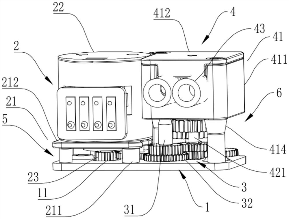
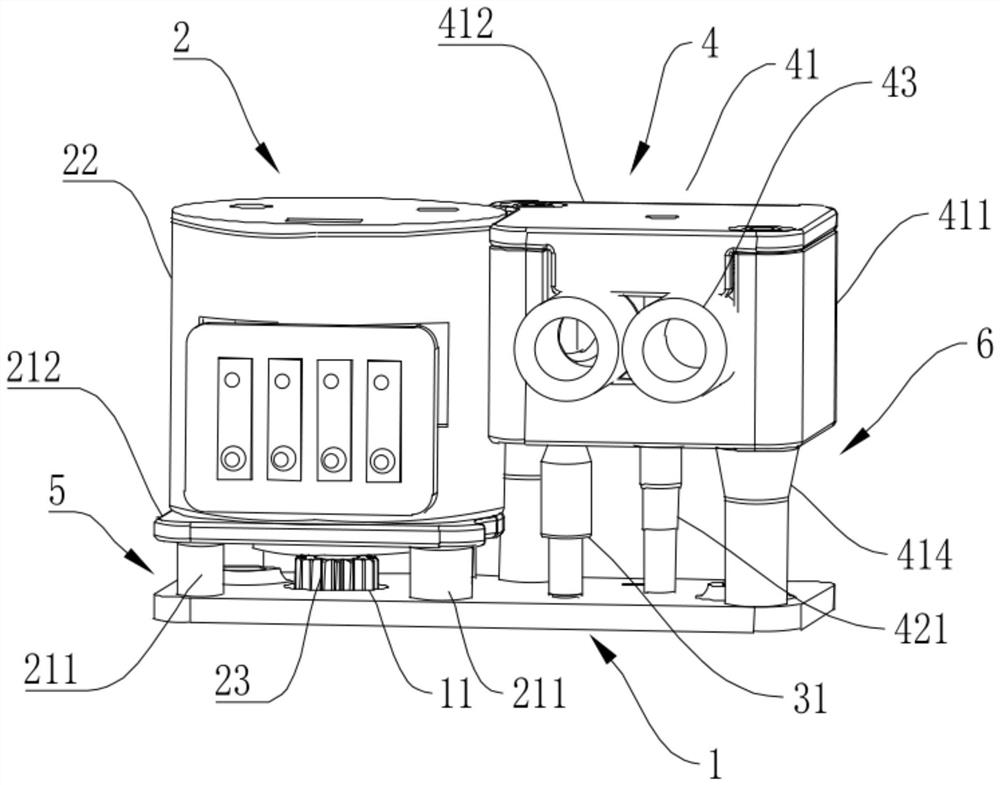
[0035] Such as figure 2 and image 3 as shown, figure 2 It is the three-dimensional structure diagram of the U-shaped electronic cigarette peristaltic pump in the first embodiment;
[0036] image 3 It is another three-dimensional structure diagram of the U-shaped electronic cigarette peristaltic pump in the first embodiment. The U-shaped electronic cigarette peristaltic pump in this embodiment includes a carrier 1, a drive component 2, a transmission component 3 and a peristaltic component 4, the drive component 2, the transmission component 3 and the peristaltic component 4 are all arranged on the carrier 1, and the drive component 2 and the transmission component 3 are arranged side by side on the same side of the carrier 1, the drive component 2 is connected to the peristaltic component 4 through the transmission component 3, and the drive component 2, the transmission component 3 and the peristaltic component 4 are integrated through the carrier 1, which is convenien...
Embodiment 2
[0045] together with reference Figure 8 , Figure 8 It is another three-dimensional structure diagram of the peristaltic power member 42 in the second embodiment. The structure of this embodiment is basically the same as that of Embodiment 1, the difference is that the creeping frame 422 is provided with a second fixing hole 4222, and the second fixing hole 4222 is located in the creeping frame 422, so the cross section of the second fixing hole 4222 is a circle, which is effective Prevent the connecting shaft 424 from falling off during assembly or use, and improve overall stability.
[0046] To sum up, through the cooperative arrangement of the bearing member, the driving component, the transmission component and the peristaltic component, the transmission component is respectively located in the first storage space and the second storage space, and then the drive component and the peristaltic component are connected. All three are set On the bearing part, the overall sha...
PUM
 Abstract
Description
Claims
Application Information