Check patentability & draft patents in minutes with Patsnap Eureka AI!

Shell-and-tube heat exchanger

A shell-and-tube heat exchanger and heat exchange tube bundle technology, which is applied in the direction of heat exchanger type, heat exchanger shell, indirect heat exchanger, etc. Large, the rigidity and toughness of the shell cannot be taken into account, etc., to solve the problems of large expansion deformation and deformation difference, low manufacturing and installation cost, and excellent heat exchange effect.

Pending Publication Date: 2021-10-12
重庆鑫顺盛达科技有限公司
View PDF3 Cites 0 Cited by
  • Summary
  • Abstract
  • Description
  • Claims
  • Application Information

AI Technical Summary

Problems solved by technology

[0006] As mentioned above, shell and tube heat exchangers have the problem that the rigidity and toughness of the shell cannot be balanced, and there are problems that the shell is easy to expand and deform and the difference in expansion and deformation is large during use. However, the existing methods to solve the expansion problem are all It is to install flexible components (such as expansion joints) on the shell to reduce or eliminate stress, but this method cannot solve the problem of large differences in shell expansion and deformation

Method used


Image

  • Shell-and-tube heat exchanger
  • Shell-and-tube heat exchanger
  • Shell-and-tube heat exchanger

Examples


Embodiment 1

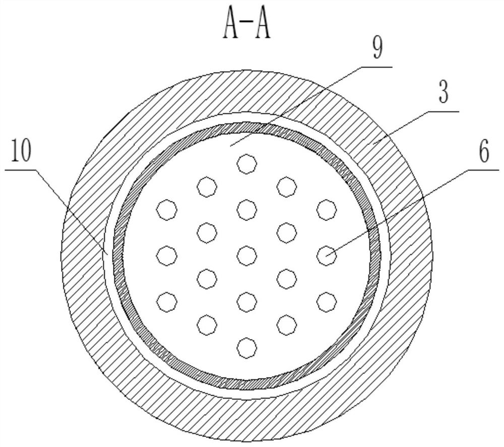
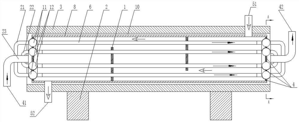
[0034] see figure 1 and figure 2 , a shell-and-tube heat exchanger, including an outer shell 3 and an inner shell 8 with the same length, the outer shell 3 is essentially a cylinder with both ends open, and the cylinder can be an integral structure or a segmented structure, It can also be an axially split structure. The outer shell 3 is provided with a support 2, and the inner cavity of the inner shell 8 is provided with a heat exchange tube bundle 6 and a baffle plate 1. All the heat exchange tube bundles 6 in the same shell are evenly arranged. The heat tube bundle 6 runs through the baffle plate 1, and the inner cavity of the heat exchange tube bundle 6 is used as the circulation channel of the heat exchange medium A, and baffles are respectively arranged at both ends of the heat exchange tube bundle 6, and the outer edge of the baffle is fixedly connected to the inner shell 8, and the baffle body 1. The heat exchange tube bundle 6 and the inner shell 8 together form a ci...

Embodiment 2

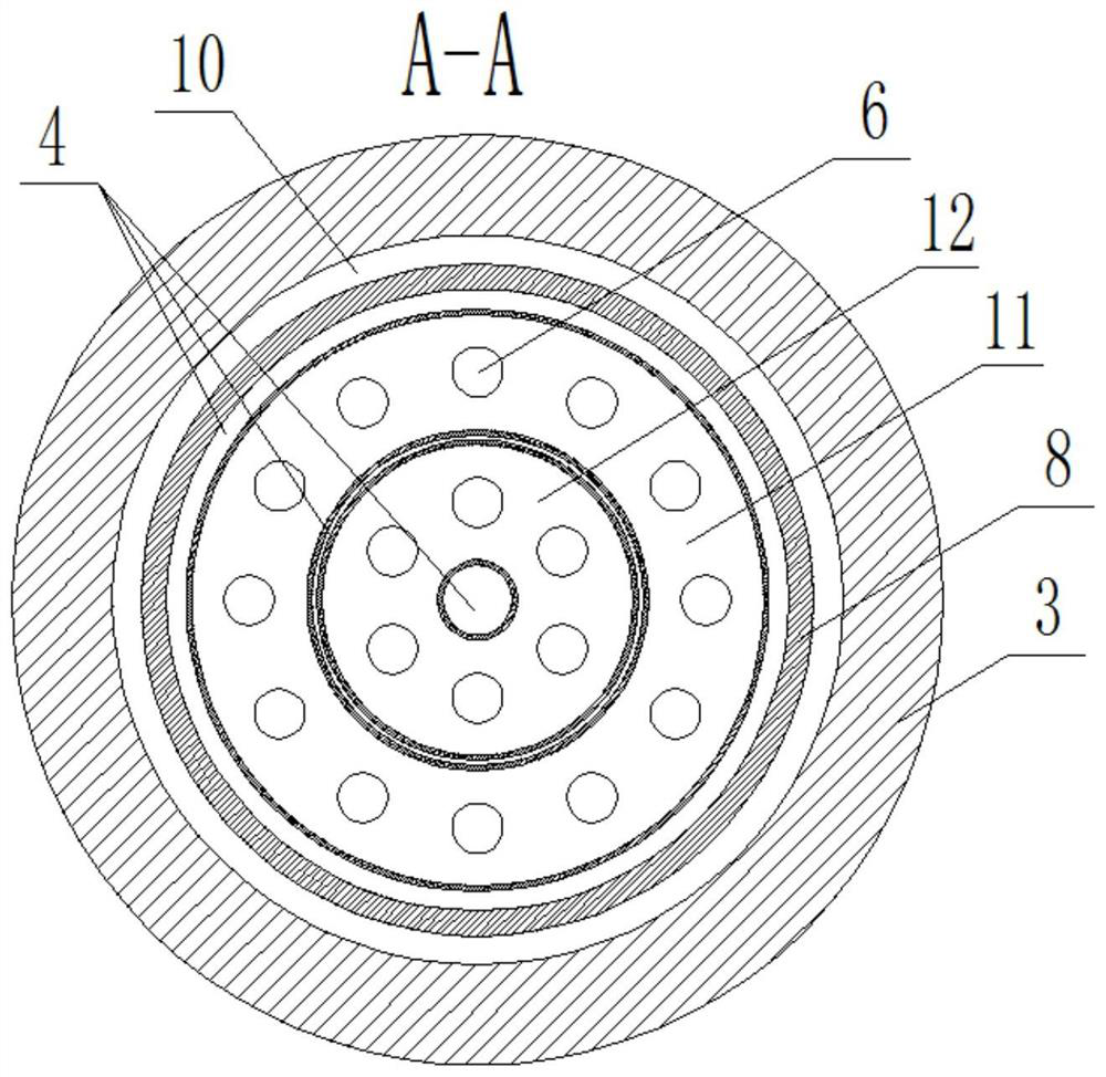
[0042] see image 3 and Figure 4 , a shell-and-tube heat exchanger, including an outer shell 3 and an inner shell 8, the inner cavity of the inner shell 8 is provided with a heat exchange tube bundle 6 and a baffle plate 1, the heat exchange tube bundle 6 runs through the baffle plate 1, and the heat exchange tube bundle 6 The inner cavity is used as the circulation channel of the heat exchange medium A, and baffles are respectively arranged at both ends of the heat exchange tube bundle 6, and the outer edge of the baffle is fixedly connected to the inner shell 8, and is jointly enclosed by the baffle body, the heat exchange tube bundle 6 and the inner shell 8. The circulation channel of the heat exchange medium B: the outer shell 3 with better rigidity is used as the pressure-bearing part and used to support the structural parts in the outer shell 3, and the inner shell 8 with better toughness is used as the sealing member and used to eliminate the stress generated by the he...

Embodiment 3

[0051] see Figure 5 , a shell-and-tube heat exchanger, including an outer shell 3 and an inner shell 8, the inner cavity of the inner shell 8 is provided with a heat exchange tube bundle 6 and a baffle plate 1, the heat exchange tube bundle 6 runs through the baffle plate 1, and the heat exchange tube bundle 6 The inner cavity is used as the circulation channel of the heat exchange medium A, and baffles are respectively arranged at both ends of the heat exchange tube bundle 6, and the outer edge of the baffle is fixedly connected to the inner shell 8, and is jointly enclosed by the baffle body, the heat exchange tube bundle 6 and the inner shell 8. The circulation channel of the heat exchange medium B: the outer shell 3 with better rigidity is used as the pressure-bearing part and used to support the structural parts in the outer shell 3, and the inner shell 8 with better toughness is used as the sealing member and used to eliminate the stress generated by the heat exchange me...


PUM


Abstract

The invention provides a shell-and-tube heat exchanger. The shell-and-tube heat exchanger comprises an outer shell and an inner shell, a heat exchange tube bundle and a baffle plate are arranged in an inner cavity of the inner shell, the heat exchange tube bundle penetrates through the baffle plate, an inner cavity of the heat exchange tube bundle serves as a circulation channel of a heat exchange medium A, blocking bodies are arranged at the two ends of the heat exchange tube bundle correspondingly, the outer edges of the blocking bodies are fixedly connected to the inner shell, the blocking bodies, the heat exchange tube bundle and the inner shell jointly define a circulation channel for containing a heat exchange medium B, the outer shell with good rigidity is adopted as a pressure bearing component and used for supporting a structural part in the outer shell, and the inner shell with good toughness is adopted as a sealing component and used for eliminating stress generated by a heat exchange medium. According to the heat exchanger, the problem that shaping and rigidity of a traditional shell-and-tube heat exchanger shell cannot be considered at the same time is solved, the problems that the traditional shell-and-tube heat exchanger shell expands and deforms, and the deformation difference is large are solved, the shell-and-tube heat exchanger is excellent in heat exchange effect, and the problems of uneven heat exchange and large heat exchange deviation do not exist in the heat exchange process.

Description

technical field [0001] The invention belongs to the field of heat exchange equipment, and in particular relates to a shell and tube heat exchanger. Background technique [0002] Most of the existing shell-and-tube heat exchangers connect the heat exchange tube bundle with the tube sheet, and then use the cylinder (shell) to wrap the heat exchange tube bundle and the tube sheet to form two independent spaces: the inner cavity of the heat exchange tube bundle And the tube box connected with it is called the tube-side space; the channel outside the heat exchange tube and the part connected with it is called the shell-side space. [0003] Such as: the shell-and-tube heat exchanger disclosed in document CN109916198A, including heat exchanger main body, hot fluid inlet, stud, sealing gasket, cold fluid outlet, outer shell, inner shell, shell fixing frame, fixing ring rod, cold fluid inlet , first flange, thermal fluid outlet, first tube box, second flange, baffle plate, heat exch...

Claims


Application Information

Patent Timeline
Patent Type & Authority Applications(China)
IPC IPC(8): F28D7/16F28F9/24F28F21/08F28F21/06
CPCF28D7/16F28F9/24F28F21/082F28F21/06
Inventor 王键
Owner 重庆鑫顺盛达科技有限公司
Features
  • R&D
  • Intellectual Property
  • Life Sciences
  • Materials
  • Tech Scout
  • Unparalleled Data Quality
  • Higher Quality Content
  • 60% Fewer Hallucinations
Learn More