Paint spraying device for machining

A technology of mechanical processing and treatment device, applied in the direction of spraying device, spraying room, etc., can solve the problems of poor quality of spraying, uneven spraying surface, insufficient spraying, etc., to prevent waste, spray uniformly, and avoid excessive extension speed. quick effect

Active Publication Date: 2021-10-15
YUHUAN FOJO ELECTRONICS CO LTD
View PDF8 Cites 0 Cited by
  • Summary
  • Abstract
  • Description
  • Claims
  • Application Information

AI Technical Summary

Problems solved by technology

[0006] Aiming at the deficiencies of the prior art, the present invention provides a paint spraying device for mechanical processing, which solves the problem that when the workpiece is sprayed with paint, it is easy to cause unevenness of the sprayed surface and insufficient paint spraying, so that the quality of the paint sprayed is poor, and it is easy to Problems that cause serious harm to the human body

Method used


Image

  • Paint spraying device for machining
  • Paint spraying device for machining
  • Paint spraying device for machining

Examples


Embodiment 1

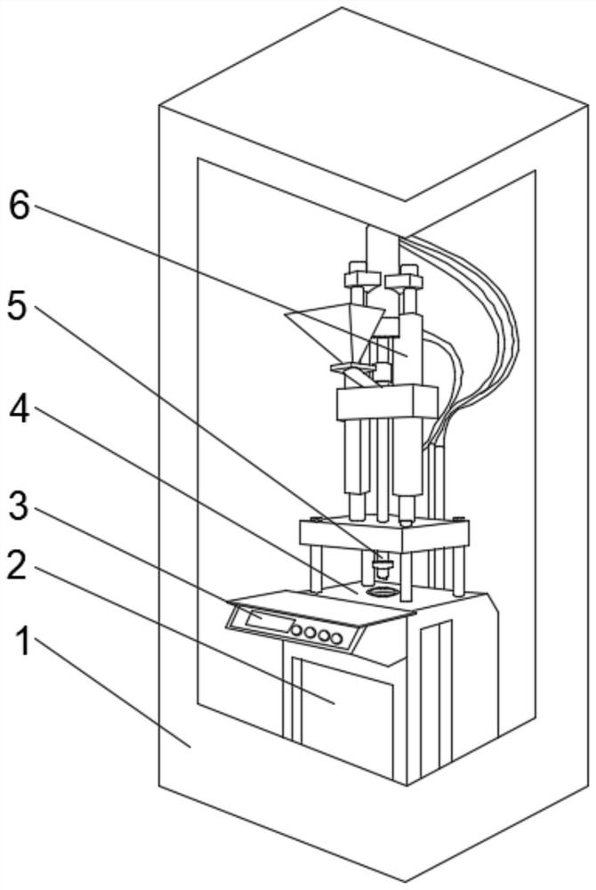
[0033] see Figure 1-2 , the present invention provides a technical solution: a paint spraying device for mechanical processing, comprising an outer frame 1, a base 2 is fixedly connected to the bottom of the inner cavity of the outer frame 1, a control panel 3 is fixedly connected to the top of the front of the base 2, the base The middle position of the top of the base 2 is provided with a processing device 4, the top of the base 2 is located on both sides of the processing device 4 and is fixedly connected with a support frame 6, and the middle position of the bottom of the support frame 6 is provided with a nozzle 5, and the top of the nozzle 5 runs through the support frame 6 and extend to the inside of the support frame 6.

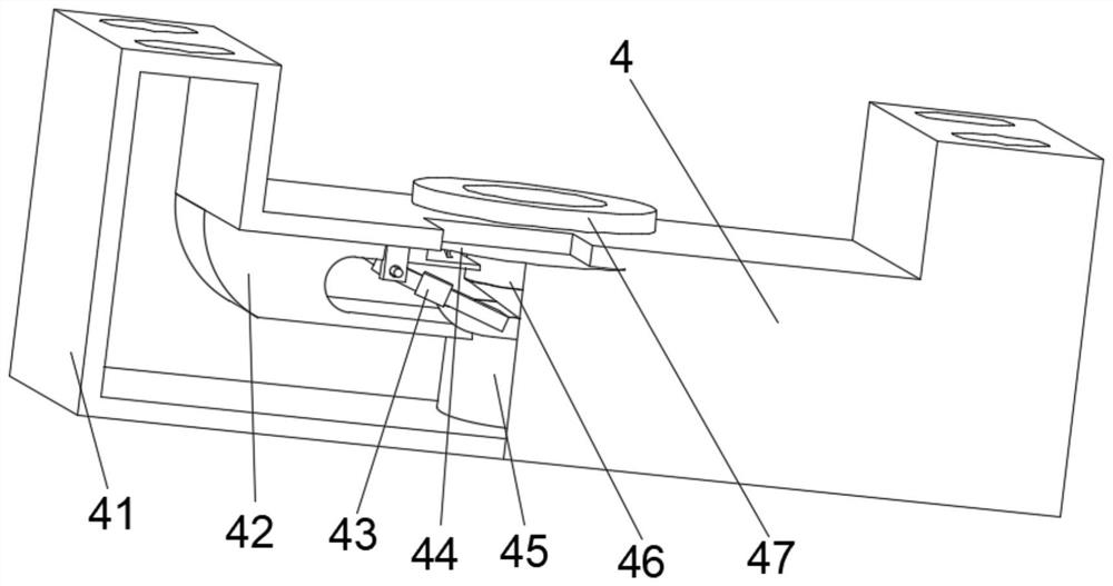
[0034] Wherein, the processing device 4 includes a shell 41, the middle position of the bottom of the inner cavity of the shell 41 is fixedly connected with a fixed seat 45, the top of the outer wall on both sides of the fixed seat 45 is fixedly conn...

Embodiment 2

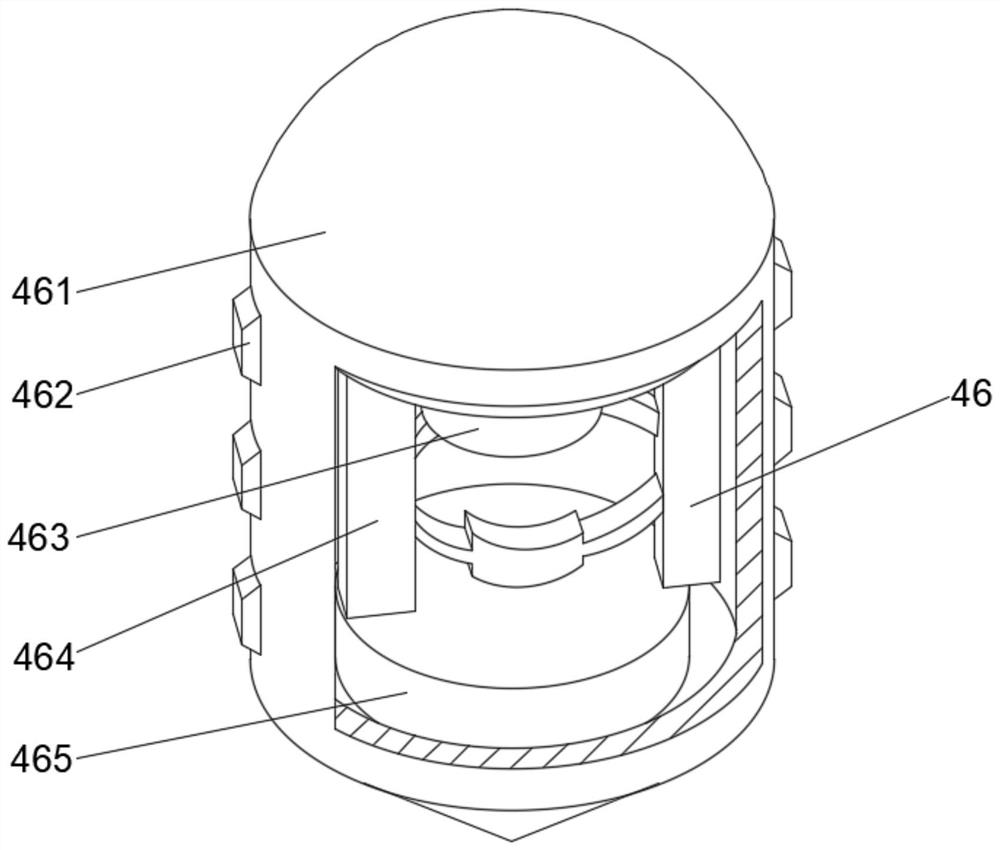
[0037] see Figure 1-4 On the basis of Embodiment 1, the present invention provides a technical solution: the blocking mechanism 46 includes a blocking block 461, the outer walls of both sides of the blocking block 461 are fixedly connected with contact blocks 462, and the top of the inner cavity of the blocking block 461 is fixedly connected with Support column 463, auxiliary mechanism 464 is fixedly connected to both sides of the bottom of support column 463, the top of auxiliary mechanism 464 runs through support column 463 and extends to the inside of support column 463, and the bottom of auxiliary mechanism 464 is fixedly connected with bottom block 465.

[0038] Wherein, the auxiliary mechanism 464 includes an adjustment block d4, the outer walls of both sides of the adjustment block d4 are provided with guide mechanisms 5, the position of the guide mechanism d5 away from the adjustment block d4 is fixedly connected with an auxiliary plate d2, and the top of the auxiliary...

Embodiment 3

[0041] see Figure 1-5 , on the basis of Embodiment 1 and Embodiment 2, the present invention provides a technical solution: the guide mechanism d5 includes a contact-increasing block d51, and the right side of the contact-increasing block d51 is fixedly connected with an upper extension plate d52, and the upper extension plate d52 The right side is provided with a balance weight d53, and the middle part of the right side of the upward extension plate d52 runs through the balance weight d53 and extends to the inside of the balance weight d53. The inner wall is fixedly connected with elastic ball d55.

[0042] When in use, when the device is moved by the extrusion force, the elastic ball d55 has good elasticity and can be dented when it is hit, thereby increasing the friction area of ​​the device, thereby ensuring the smooth progress of the painting work and increasing contact The protrusions on the surface of the board d54 will engage when moving, thereby increasing the conta...


PUM


Abstract

The invention discloses a paint spraying device for machining, which comprises an outer frame, a base is fixedly connected to the bottom of an inner cavity of the outer frame, a control panel is fixedly connected to the top of the front face of the base, a processing device is arranged in the middle of the top of the base, supporting frames are fixedly connected to the positions, located on the two sides of the processing device, of the top of the base, and spray heads are arranged in the middles of the bottoms of the supporting frames. The invention relates to the technical field of machining. According to the paint spraying device for machining, the situation that a workpiece is difficult to take out due to the fact that the device is prone to adhering to the workpiece is effectively avoided, so that spraying of the workpiece is more uniform, and the machined workpiece is convenient to disassemble and clamp; and the fixing base has good stability, so that the device is not prone to excessively inclining in the adjusting process, the environment pollution is avoided, the paint spraying condition in a box body is effectively observed, adjustment is carried out in time, the waste of spray paint is prevented, and the body health of workers is conveniently protected.

Description

technical field [0001] The invention relates to the technical field of machining, in particular to a paint spraying device for machining. Background technique [0002] Machining refers to the process of changing the shape or performance of a workpiece through a mechanical device. According to the difference in processing methods, it can be divided into cutting processing and pressure processing, which refers to the whole process of making products from raw materials (or semi-finished products). For machine production, it includes transportation and storage of raw materials, production preparation, blank manufacturing, processing and heat treatment of parts, product assembly, debugging, painting and packaging, etc. [0003] According to the Chinese Patent No. CN111760702A, a plate grinding and painting device for mechanical processing realizes the longitudinal processing of the plate by controlling the movement of the pneumatic slider. A hot air blower is set to generate hot...

Claims


Application Information

Patent Timeline
Patent Type & Authority Applications(China)
IPC IPC(8): B05B13/02B05B14/00B05B16/40
CPCB05B13/0285B05B14/00B05B16/40Y02P70/10
Inventor 赵猛
Owner YUHUAN FOJO ELECTRONICS CO LTD
Why Eureka
Try Eureka