Mold for metal casting molding

A metal casting and mold technology, applied in the field of metal casting molds, can solve the problems of inconvenient installation and use of stamping molds, affecting the efficiency of stamping mold installation, consuming physical strength of operators, etc.

Active Publication Date: 2021-10-15
江西维海机械设备有限公司
View PDF5 Cites 0 Cited by
  • Summary
  • Abstract
  • Description
  • Claims
  • Application Information

AI Technical Summary

Problems solved by technology

[0003] However, the following problems exist in the application of existing stamping dies: when the stamping head impacts the metal, because the lower part of the stamping head is uneven, the metal fragments or Debris will be adsorbed or stuck on the lower part of the stamping head, and it is necessary to use the power structure to remove it. The installation and use of the power structure will increase the production and use costs of the stamping die, making the stamping die not in line with the concept of green environmental protection development. Secondly, due to stamping The mold is made of hard metal, so its own weight is relatively large. When the operator replaces the stamping mold, it needs to lift and move the stamping mold for a long time, which will accelerate the consumption of the operator's physical strength and bring inconvenience to the installation and use of the stamping mold. Finally, the replacement When forming the template, it is necessary to complete the alignment connection between the guide rod and the conduit. Because the internal cross-sectional size of the conduit is small, it is difficult to complete the alignment connection between the guide rod and the conduit at one time. Multiple alignment adjustments will affect the installation efficiency of the stamping die

Method used


Image

  • Mold for metal casting molding
  • Mold for metal casting molding
  • Mold for metal casting molding

Examples


Embodiment Construction

[0035] In order to further illustrate the various embodiments, the present invention provides accompanying drawings, which are part of the disclosure of the present invention, and are mainly used to illustrate the embodiments, and can be used in conjunction with the relevant descriptions in the specification to explain the operating principles of the embodiments, for reference Those of ordinary skill in the art should be able to understand other possible implementations and advantages of the present invention. The components in the figures are not drawn to scale, and similar component symbols are generally used to represent similar components.

[0036] According to an embodiment of the present invention, a mold for metal casting is provided.

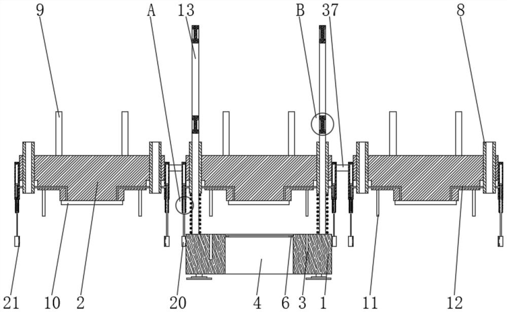
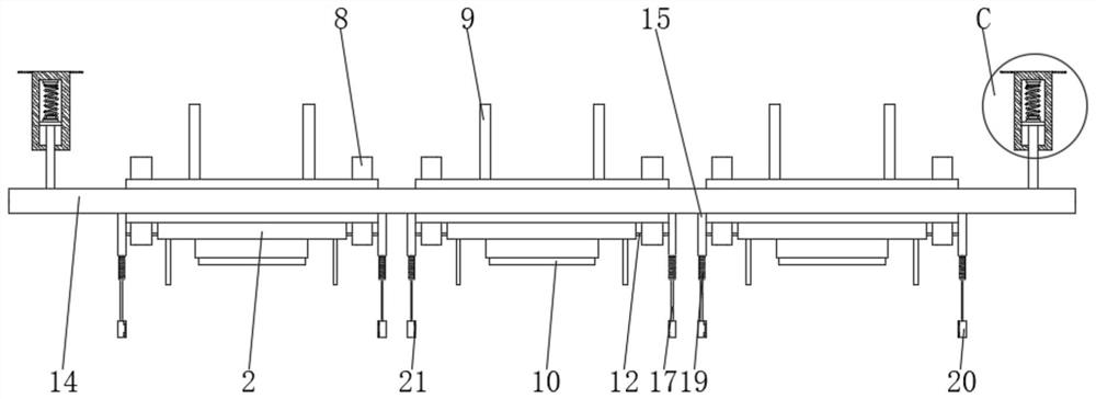
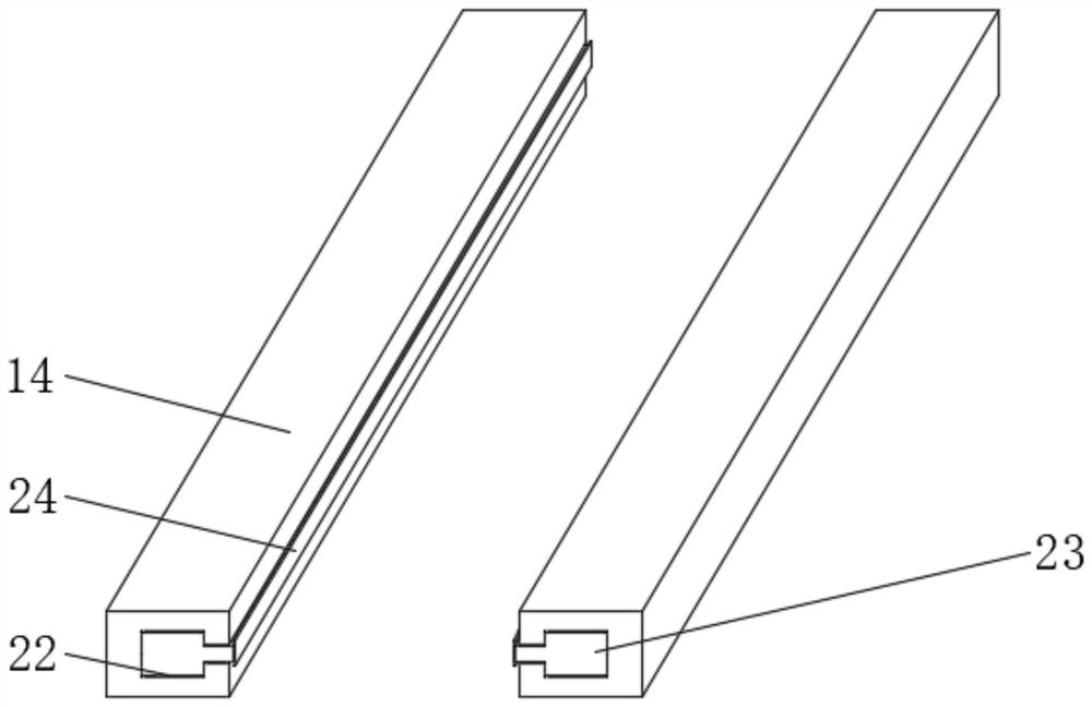
[0037] Now in conjunction with accompanying drawing and specific embodiment the present invention is further described, as Figure 1-8 As shown, a mold for metal casting molding according to an embodiment of the present invention include...


PUM


Abstract

The invention discloses a mold for metal casting molding. The mold comprises a lower mold plate and an upper mold plate, wherein two sets of alignment grooves, a stamping groove and two sets of guide rods are arranged at the upper part of the lower mold plate; a limiting frame is fixedly installed in the stamping groove; damping springs sleeve the side walls of the two sets of guide rods; two guide pipes and two sets of connecting rods are arranged at the upper part of the upper mold plate; a stamping head and two sets of abutting plates are fixedly installed at the lower part of the upper mold plate; a plurality of blowing air pipes are installed in the upper mold plate; alignment steel cables are installed above the two sets of guide rods; and replacement clamping plates are installed at the front part and the rear part of the upper mold plate. The mold has the beneficial effects that cleaning work of the stamping head can be automatically completed through the blowing air pipes without an electric power structure, so that consumption of electric power resources is reduced, meanwhile, the production and installation cost is reduced, and the mold for metal casting molding conforms to the concept of green and environment-friendly development.

Description

technical field [0001] The invention relates to the technical field of metal casting molds, in particular to a mold for metal casting. Background technique [0002] Metal parts refer to the collective name of metal blocks, metal rods, metal pipes, etc. of various specifications and shapes made of metal materials. The casting of metal parts is now mostly made of stamping dies. A special process equipment processed into parts, which is widely used in the fields of home appliances, electronic communications, automobiles and other parts manufacturing. In actual use, it has the advantages of simple operation, stable stamping and high product qualification rate. [0003] However, the following problems exist in the application of the existing stamping dies: when the stamping head hits the metal, because the lower part of the stamping head is uneven, some of the metal fragments or chips that are knocked out will be adsorbed or clamped on the lower part of the stamping head, requiri...

Claims


Application Information

Patent Timeline
Patent Type & Authority Applications(China)
IPC IPC(8): B22D18/02
CPCB22D18/02Y02P70/10
Inventor 李根吴谦杨丹
Owner 江西维海机械设备有限公司
Why Eureka
Try Eureka