
Real-time fault diagnosis method and system based on sequential random forest

A random forest, real-time fault technology, applied in random CAD, computer parts, character and pattern recognition, etc., can solve the problems of high missed diagnosis rate and misdiagnosis rate, failure to realize fault diagnosis, etc., to alleviate the missed diagnosis rate and misdiagnosis rate bias. High, real-time adaptive multi-sample fault diagnosis effect

Active Publication Date: 2021-10-15
BEIHANG UNIV
View PDF6 Cites 0 Cited by
  • Summary
  • Abstract
  • Description
  • Claims
  • Application Information

AI Technical Summary

Problems solved by technology

[0004] In view of this, the object of the present invention is to provide a real-time fault diagnosis method and system based on sequential random forest, so as to alleviate the existing technologies in the prior art that cannot realize real-time fault diagnosis and have high rates of missed diagnosis and misdiagnosis question

Method used


Image

  • Real-time fault diagnosis method and system based on sequential random forest
  • Real-time fault diagnosis method and system based on sequential random forest
  • Real-time fault diagnosis method and system based on sequential random forest

Examples


Embodiment 1

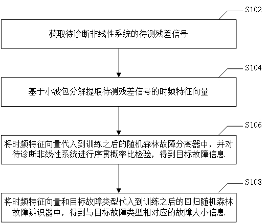
[0023] figure 1 It is a flow chart of a sequential random forest-based real-time fault diagnosis method provided according to an embodiment of the present invention, and the method is applied to fault detection of a nonlinear system. like figure 1 As shown, the method specifically includes the following steps:

[0024] Step S102, acquiring the residual signal to be measured of the nonlinear system to be diagnosed.

[0025] Step S104, extracting the time-frequency feature vector of the residual signal to be measured based on wavelet packet decomposition.

[0026] In step S106, the time-frequency feature vector is substituted into the trained random forest fault separator, and a sequential probability ratio test is performed on the nonlinear system to be diagnosed to obtain target fault information. Wherein, the target fault information includes target fault type and target fault occurrence time.

[0027] In step S108, the time-frequency feature vector and the target fault t...

Embodiment 2

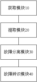
[0116] image 3 is a schematic diagram of a sequential random forest-based real-time fault diagnosis system provided according to an embodiment of the present invention. Such as image 3 As shown, the system includes: an acquisition module 10 , an extraction module 20 , a fault isolation module 30 and a fault identification module 40 .

[0117] Specifically, the acquiring module 10 is configured to acquire the residual signal to be measured of the nonlinear system to be diagnosed.

[0118] Optionally, the obtaining module 10 is also used to: establish a nominal model of the nonlinear system to be diagnosed, and obtain a nominal system residual signal of the nominal model; obtain an observation residual signal of the nonlinear system to be diagnosed; The system residual signal and the observation residual signal are used to obtain the residual signal to be measured.

[0119] Specifically, the residual signal to be tested is determined by the following formula: e l =e s -g(...


PUM


Abstract

The invention provides a real-time fault diagnosis method and system based on a sequential random forest. The method comprises: obtaining a to-be-detected residual signal of a to-be-diagnosed nonlinear system; extracting a time-frequency feature vector of the residual signal to be measured based on wavelet packet decomposition; substituting the time-frequency feature vector into a trained random forest fault separator, and performing sequential probability ratio test on the to-be-diagnosed nonlinear system to obtain target fault information, wherein the target fault information comprises a target fault type and target fault occurrence time; and substituting the time-frequency feature vector and the target fault type into a trained regression random forest fault identifier to obtain fault size information corresponding to the target fault type. The technical problems that in the prior art, real-time fault diagnosis cannot be achieved, and the missed diagnosis rate and the misdiagnosis rate are high are solved.

Description

technical field [0001] The invention relates to the technical field of UAV fault diagnosis, in particular to a real-time fault diagnosis method and system based on sequential random forest. Background technique [0002] Existing quantitative analysis fault diagnosis methods can be roughly divided into analytical model-based and data-driven methods. The core idea of ​​fault diagnosis based on analytical model is to estimate the observed values ​​of system variables through the state, and use the residual error between it and the true value of the system state variables as the source and basis of diagnosis. Residuals are usually obtained in the following two ways: based on state observers and based on reference models. The key to the former is to design observers and filters with strong filtering and high dynamic response characteristics. The difficulty of the latter is to construct accurate high-dimensional nonlinear System nominal model. To a certain extent, the estimation...

Claims


Application Information

Patent Timeline
IPC IPC(8): G06F30/15G06F30/27G06K9/62G06N3/00G06F111/08
CPCG06F30/15G06F30/27G06N3/006G06F2111/08G06F18/214G06F18/24323
Inventor 宋佳艾绍洁赵凯苏江城尚维泽蔡国飙
Owner BEIHANG UNIV
Learn More