
Deep well grounding device for high soil resistivity area

A soil resistivity and grounding device technology, applied in the direction of connecting contact materials, etc., can solve the problems of affecting the operation stability, unable to adjust the length, and dust off the well wall, etc., to achieve good support and fixation, avoid soil loss, and ensure protection. effect of effect

Active Publication Date: 2021-10-15
新疆瑞特电子工程技术有限公司
View PDF8 Cites 0 Cited by
  • Summary
  • Abstract
  • Description
  • Claims
  • Application Information

AI Technical Summary

Problems solved by technology

[0004] However, the existing deep well grounding device still has the problems of poor protection effect, easy to cause the dust on the well wall to fall off, inconvenient support and fixation, affecting operational stability, and inability to protect in rainy days, prone to soil loss and inability to adjust the length.

Method used


Image

  • Deep well grounding device for high soil resistivity area
  • Deep well grounding device for high soil resistivity area
  • Deep well grounding device for high soil resistivity area

Examples


Embodiment Construction

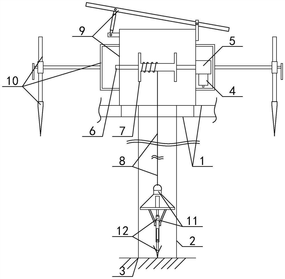
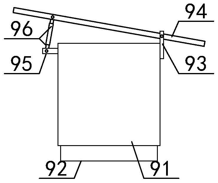
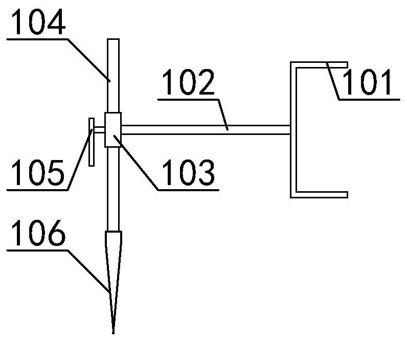
[0033] The present invention is described in detail below in conjunction with accompanying drawing, as appended figure 1 And attached figure 2 As shown, the deep well grounding device in the high soil resistivity area includes a foundation 1, a deep well body 2, a well bottom 3, a lifting motor 4, a worm gear reducer 5, a rotating shaft 6, a winding wheel 7 and a lifting rope 8, the The inside of the foundation 1 is provided with a deep well body 2; the bottom of the deep well body 2 is set as the well bottom 3; the lifting motor 4 is bolted to the lower end of the worm gear reducer 5; the output of the worm gear reducer 5 The shaft coupling is connected to the right end of the rotating shaft 6; the outer wall of the rotating shaft 6 is sleeved with a winding wheel 7, and the key is connected; the outer surface of the winding wheel 7 is wound with a lifting rope 8, which can ensure the grounding effect , so as to ensure grounding stability and facilitate lifting and maintena...


PUM


Abstract

The invention provides a deep well grounding device for a high soil resistivity area, which comprises a foundation, a deep well body, a well bottom, a lifting motor, a worm gear reducer, a rotating shaft, a winding wheel and a lifting rope, and is characterized in that the deep well body is arranged in the foundation; a well bottom is arranged at the bottom of the deep well body; the lifting motor is in bolted connection with the lower end of the worm gear reducer; and an output shaft coupling of the worm gear reducer is connected with the right end of the rotating shaft. Through the arrangement of the outer pile casing, the mounting pipe, the vertical seat, the rainproof guide plate, the connecting seat and the telescopic adjusting rod, the problem of soil loss in rainy days can be avoided, well mouth soil of the deep well body can be protected through the outer pile casing and the mounting pipe, soil loss is avoided, and the action position of the telescopic adjusting rod in the connecting seat is adjusted in a telescopic mode. The rainproof guide plate can move in the interior between the vertical seats, and after the protection angle is determined, rainproof and flow guiding work can be carried out, so that the protection effect is guaranteed.

Description

technical field [0001] The invention belongs to the technical field of grounding electrodes, in particular to deep well grounding devices in areas with high soil resistivity. Background technique [0002] The deep well grounding electrode refers to a vertical grounding body that first drills a hole through a deep well, then puts a vertical grounding electrode of the same length as the design depth into the hole, fills the gap with a low-resistivity material, and finally achieves the purpose of effectively reducing the grounding resistance. [0003] At present, deep well grounding devices in areas with high soil resistivity are widely used. [0004] However, the existing deep well grounding device still has the problems of poor protection effect, easy to cause the dust on the well wall to fall off, inconvenient support and fixation, affecting operational stability, failure of protection in rainy days, prone to soil loss and inability to adjust the length. [0005] Therefore,...

Claims


Application Information

Patent Timeline
IPC IPC(8): H01R4/66
CPCH01R4/66
Inventor 马亚伟胡东北
Owner 新疆瑞特电子工程技术有限公司
Learn More