Novel soil turning machine for agricultural planting

A soil-turning machine and agricultural technology, applied in agricultural machinery and implements, agriculture, soil preparation machinery, etc., can solve the problems of affecting the progress of sowing, time-consuming and labor-intensive, etc., to prevent soil loss, good compaction effect, and prevent soil erosion. collapse effect

Active Publication Date: 2022-04-12
SHANDONG YUAN QUAN MACHINERY
View PDF5 Cites 0 Cited by
  • Summary
  • Abstract
  • Description
  • Claims
  • Application Information

AI Technical Summary

Problems solved by technology

[0002] When sowing related crops on the field ridges, it is necessary to turn over the field ridges before sowing, remove the weeds growing on the soil, and loosen the soil, which is suitable for seeds to germinate and grow; After turning the soil, it is necessary to manually pat and pack the edge of the turned field ridge, which not only consumes time and labor, but also affects the progress of the sowing work.

Method used


Image

  • Novel soil turning machine for agricultural planting
  • Novel soil turning machine for agricultural planting
  • Novel soil turning machine for agricultural planting

Examples


Embodiment Construction

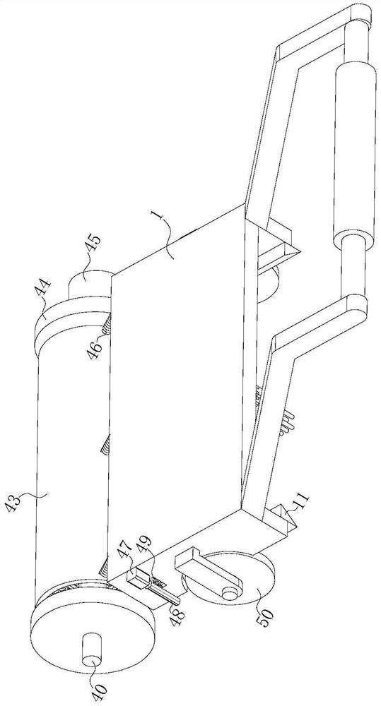
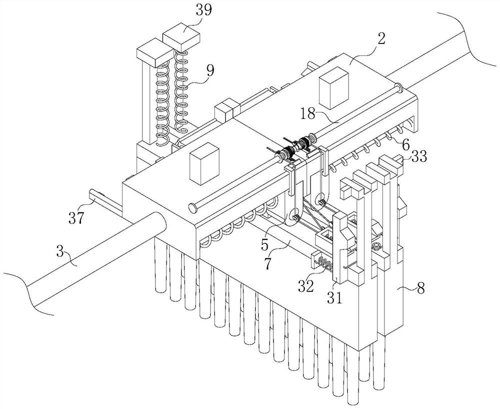
[0034] see Figure 1-12, the present invention provides a technical solution: a new type of soil-turning machine for agricultural planting, including a housing 1, the left side of the housing 1 is provided with a crushing assembly, and the bottom of the housing 1 is slidingly connected with two symmetrical Arranged mounting plate 2, the housing 1 is rotatably connected with a two-way threaded rod 3, the two mounting plates 2 are respectively threaded with two ends of the two-way threaded rod 3, and the housing 1 is fixedly connected with a first Motor 4, the output shaft of the first motor 4 is fixedly connected with the two-way threaded rod 3, the bottom of the mounting plate 2 is slidably connected with the first slide plate 5, and the first slide plate 5 is fixedly connected with a button for its reset. The first spring 6, the first slide plate 5 is rotatably connected with a rake bar 7, and the rake bar 7 is slidably connected with a clapper 8; the clapper 8 is fixedly con...


PUM


Abstract

The invention discloses a theme in the technical field of agricultural planting. Each driving assembly comprises a clamping groove, a triangular push block, a first air cylinder and a limiting cancelling part. The clamping groove is formed in the beating plate, the side edge of the clamping groove is provided with a limiting block capable of limiting the clamping groove, the limiting block is slidably connected with a second sliding plate, and the second sliding plate is fixedly connected to the top of the rake rod; the limiting block is fixedly connected with a third spring used for resetting the limiting block. The triangular push block is fixedly connected to the shell and used for driving the beating plate to move downwards so that the clamping groove can be in butt joint with the limiting block. The fixed end of the first air cylinder is slidably connected to the side wall of the mounting plate in the vertical direction, the telescopic end of the first air cylinder is fixedly connected with a push plate, and the push plate is used for driving the first sliding plate to move; the edge of the field ridge is repeatedly flapped, the edge of the field ridge can be tamped, soil on the edge of the field ridge can be prevented from collapsing, the tamping effect on the edge of the field ridge is better, and soil loss on the edge of the field ridge can be prevented.

Description

technical field [0001] The invention relates to agricultural planting, in particular to a novel soil-turning machine for agricultural planting. Background technique [0002] When sowing related crops on the field ridges, it is necessary to turn over the field ridges before sowing, remove the weeds growing on the soil, and loosen the soil, which is suitable for seeds to germinate and grow; After turning the soil, it is necessary to manually pat and pack the edge of the turned field ridge, which not only consumes time and labor, but also affects the progress of the sowing work. [0003] Based on this, the present invention has designed a kind of novel tillage machine for agricultural planting, to solve the above problems. Contents of the invention [0004] The purpose of the present invention is to provide a new type of soil-turning machine for agricultural planting to solve the problems raised in the above-mentioned background technology. [0005] In order to achieve the ...

Claims


Application Information

Patent Timeline
IPC IPC(8): A01B49/02A01B19/06A01B23/02A01B35/02A01B35/18A01B35/26A01B35/28
CPCY02W30/40
Inventor 王永盛王强王永禄王永福王学文
Owner SHANDONG YUAN QUAN MACHINERY
Why Eureka
Try Eureka