NOX reduction catalyst
A denitration catalyst and catalyst technology, applied in the field of denitration catalysts, can solve the problems of deactivation of the reaction active point of the denitration catalyst, the removal of the denitration catalyst, and the reduction of the efficiency of denitration, and achieve stress reduction, excellent wear resistance, and denitration efficiency. Reduce the effect of inhibition
- Summary
- Abstract
- Description
- Claims
- Application Information
AI Technical Summary
Problems solved by technology
Method used
Image
Examples
Embodiment 1
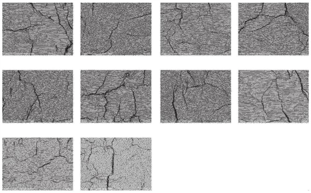
[0079] Molybdenum trioxide, ammonium metavanadate, and silica sol were added to titanium oxide powder, and aluminum compound powder and aluminosilicate fibers were further added, and kneaded while adjusting the water content to obtain a catalyst paste. The amount of moisture is adjusted so that microcracks are uniformly formed. This is coated on an expanded metal, followed by press processing to obtain a flat plate-shaped molded product. This molded product was dried at 120° C. for 1 hour. Next, it was placed in a firing furnace, and the temperature was raised from room temperature to 500° C. over 2 hours, maintained at 500° C. for 2 hours, and then cooled to room temperature over 2 hours to obtain a molded body. Each observation image in 10 randomly selected regions of the surface of the obtained compact is shown in figure 1 middle.
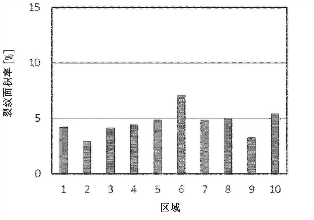
[0080] The microcracks spread in a network on the surface of the molded body in any region. 95% crack width B of microcracks 95 The averag...
Embodiment 2
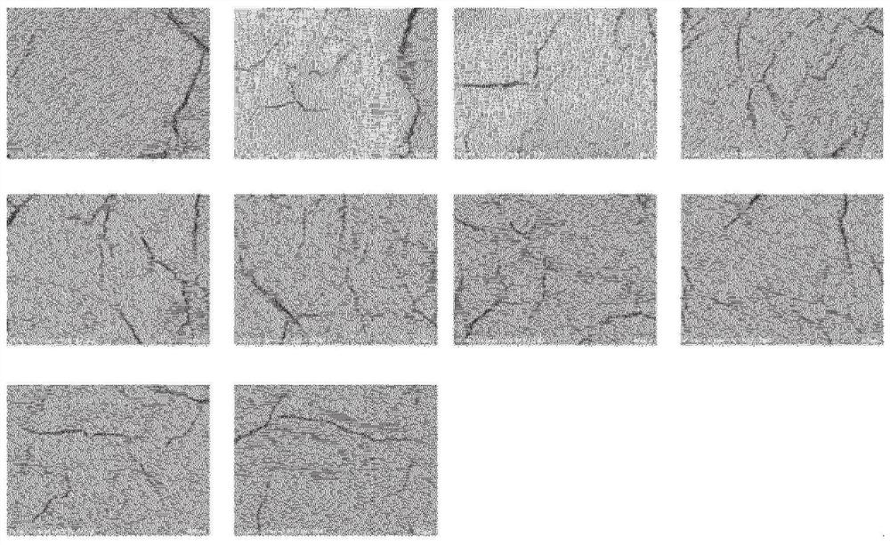
[0083] Dry the molded product at 30°C for 12 hours, then place it in a firing furnace, raise the temperature from room temperature to 500°C over 12 hours, maintain it at 500°C for 2 hours, and then cool it to room temperature over 12 hours. Except for this, a denitration catalyst was obtained by the same method as in Example 1. Each observation image in 10 randomly selected regions of the surface of the obtained compact is shown in image 3 middle.
[0084] The microcracks spread in a network on the surface of the molded body in any region. 95% crack width B of microcracks 95 The average value of the crack area ratio was 30 μm, 3.19%, and the coefficient of variation of the crack area ratio was 0.21. This molded body was used as a denitration catalyst. In addition, the wear relative decrement is 0.30.
Embodiment 3
[0086]A denitration catalyst was obtained by the same method as in Example 1 except that the water content, drying conditions, and firing conditions were changed. Each observation image in 10 randomly selected regions of the surface of the obtained compact is shown in Figure 5 middle.
[0087] Microcracks propagate in any region in the shape of a double-sided comb on the surface of the shaped body. 95% crack width B of microcracks 95 The average value of the crack area ratio was 90 μm, 12.27%, and the coefficient of variation of the crack area ratio was 0.08. This molded body was used as a denitration catalyst. In addition, the wear relative reduction was 0.34.
PUM
| Property | Measurement | Unit |
|---|---|---|
| width | aaaaa | aaaaa |
| width | aaaaa | aaaaa |
| thickness | aaaaa | aaaaa |
Abstract
Description
Claims
Application Information
 - R&D
- Intellectual Property
- Life Sciences
- Materials
- Tech Scout
- Unparalleled Data Quality
- Higher Quality Content
- 60% Fewer Hallucinations
Browse by: Latest US Patents, China's latest patents, Technical Efficacy Thesaurus, Application Domain, Technology Topic, Popular Technical Reports.
© 2025 PatSnap. All rights reserved.Legal|Privacy policy|Modern Slavery Act Transparency Statement|Sitemap|About US| Contact US: help@patsnap.com


